
CNC Machining Tolerances Guide: Standards, GD&T and Tight-Tolerance Design
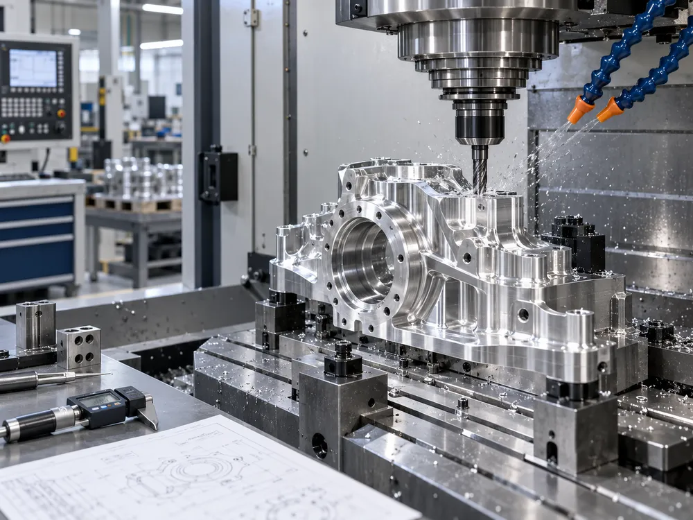
CNC machining tolerances define how much a finished feature may vary from its specified dimension or geometry. For engineers and buyers, understanding tolerance is essential because tighter requirements affect manufacturability, inspection, lead time, and cost.
CNC machining tolerance is the permitted variation between a specified dimension or geometric requirement and the finished feature. There is no single universal CNC tolerance that applies to every machine, supplier, material, or part. Practical tolerance depends on feature geometry, material, workholding, tooling, setup strategy, machine capability and condition, thermal stability, and the measurement method used to verify the result.
A good tolerance strategy therefore starts with part function, not with the smallest number a machine can theoretically achieve.
What Are CNC Machining Tolerances?
A tolerance defines an acceptable range of variation.
If a drawing specifies:
20.000 mm ±0.005 mm
the acceptable dimensional range is:
19.995 mm to 20.005 mm
The nominal dimension is 20.000 mm, while the total tolerance zone is 0.010 mm wide.
This is a bilateral tolerance because variation is permitted in both directions.
A tolerance may also be unilateral. For example:
20.000 mm +0.010 / -0.000 mm
allows the feature to be larger than the nominal dimension but not smaller.
Engineers use different tolerance methods depending on function.
A dimensional tolerance may control a diameter, length, thickness, or gap. Geometric tolerances can control form, orientation, location, or runout.
The important point is that tolerance is not simply a statement about machine precision.
It is a functional engineering requirement that must be manufactured and inspected.
What Is a Standard CNC Machining Tolerance?
There is no single universal “standard CNC machining tolerance.”
The phrase can refer to several different things, and confusing them can cause problems during quoting or inspection.
| Tolerance Type | What It Means | Typical Use |
|---|---|---|
| Shop Default Tolerance | A supplier’s own default when no tighter requirement is specified | General commercial machining |
| General Drawing Tolerance | A tolerance system applied to unspecified dimensions on a drawing | Engineering drawings |
| Feature-Specific Tolerance | A tolerance explicitly assigned to a critical feature | Fits, sealing, alignment, precision interfaces |
Shop Default Tolerance
A machining supplier may publish a default tolerance for certain CNC services.
That value reflects the supplier’s own process, equipment, commercial offering, and inspection approach.
It should not be treated as a universal CNC industry standard.
Two suppliers may publish different default tolerances while both operate capable CNC equipment.
General Drawing Tolerance
Engineering drawings may include a general tolerance note that applies when an individual dimension does not have its own tolerance.
This allows the drawing to avoid adding a separate tolerance to every dimension.
General tolerance systems may reference a company standard, customer standard, or an external standard such as ISO 2768 where appropriate.
Feature-Specific Tolerance
Critical features should normally be toleranced according to function.
Examples include:
- Bearing fits
- Precision bores
- Locating diameters
- Sealing surfaces
- Mating interfaces
- Critical hole positions
- Alignment features
An individually specified tolerance takes priority over a broader general tolerance for that feature.
For engineering and purchasing teams, this distinction matters because supplier default tolerance, general drawing tolerance, and feature-specific tolerance are not interchangeable concepts.
Why Is There No Single Standard CNC Tolerance?
CNC machining covers too many combinations of geometry, material, process, machine type, and inspection method for one number to describe every situation accurately.
A tolerance that is straightforward on one feature may be difficult on another.
For example, controlling a short rigid diameter is very different from controlling:
- A long thin wall
- A deep internal bore
- A flexible plastic component
- A feature reached by a long cutting tool
- A dimension transferred across multiple setups
The supplier also has to consider how the feature will be measured.
A requirement that cannot be verified reliably is not a useful manufacturing specification.
One important principle is:
Machine positioning capability does not automatically equal guaranteed finished-part tolerance.
A machine specification may describe axis positioning or repeatability under defined conditions.
The finished part is also affected by tooling, tool wear, workholding, material behavior, thermal effects, setup strategy, cutting forces, feature geometry, and measurement uncertainty.
For that reason, machine specifications should not be converted directly into blanket part-tolerance promises.
What Is a Reasonable Machining Tolerance?
The most reasonable machining tolerance is generally the loosest tolerance that still allows the part to perform its intended function.
A tolerance should support a real engineering need.
That may include:
- Assembly
- Fit
- Sealing
- Alignment
- Motion
- Bearing performance
- Interchangeability
- Positional control
- Functional clearance
If a tolerance is too loose, the part may not work correctly.
If it is unnecessarily tight, the supplier may need additional machining, slower finishing passes, more stable workholding, tighter thermal control, and more detailed inspection.
This can increase manufacturing cost without improving part performance.
The goal is therefore not to specify the smallest tolerance possible.
It is to specify the correct tolerance for the function.
For more detail on how tolerance affects quotation, see our CNC Machining Cost Guide.
What Factors Affect CNC Machining Tolerances?
Tolerance capability is the result of the complete manufacturing system.
| Factor | Effect on Tolerance Control |
|---|---|
| Material | Thermal movement, internal stress, cutting behavior |
| Feature geometry | Rigidity, accessibility, distortion risk |
| Workholding | Clamping stability and datum consistency |
| Tooling | Deflection, wear, reach and cutting stability |
| Setups | Repositioning and datum transfer |
| Heat | Workpiece, tool and machine expansion |
| Machine capability | Process capability boundary |
| Inspection | Ability to verify the specified requirement |
These factors interact with each other.
A rigid aluminum block with accessible features may behave very differently from a thin PEEK component or a titanium part requiring long-reach tooling.
How Does Part Geometry Affect Tolerance?
Geometry can make the same numerical tolerance either straightforward or difficult.
Thin Walls
Thin walls can move under clamping and cutting forces.
They may also relax or distort after material is removed.
Maintaining a tight dimension on a thin section may therefore require lighter cutting, different workholding, staged machining, or additional finishing.
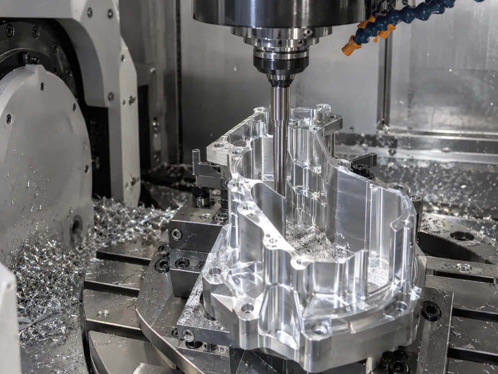
Deep Pockets
Deep pockets often require longer tools.
Long tool overhang reduces rigidity and can increase vibration and deflection.
This can affect wall position, bottom geometry, and surface quality.
Deep Bores
Deep precision bores can be challenging because tool stiffness, heat, chip evacuation, and measurement access become more difficult as depth increases.
A tolerance that is practical on a shallow bore may be harder to maintain on a deep one.
Long Features
Long shafts, rails, walls, or other extended features may respond to cutting forces and thermal expansion differently from short rigid features.
Straightness, parallelism, and dimensional stability may all require additional consideration.
Difficult Tool Access
When a feature is difficult to reach, the supplier may need longer tools, special tooling, additional setups, or a different machine configuration.
Each change can influence process stability.
How Does Material Affect Machining Tolerance?
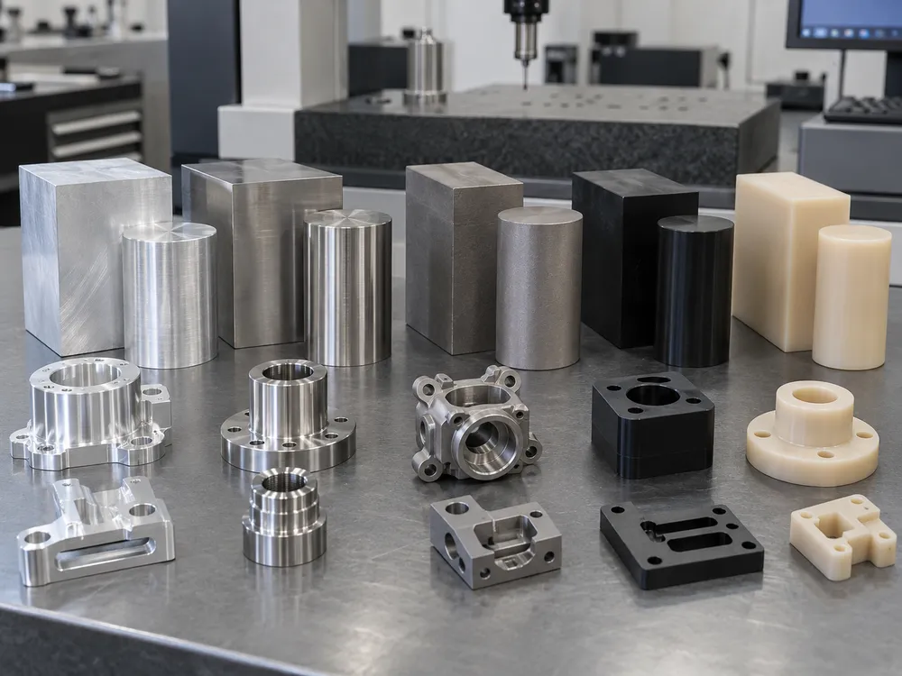
Different materials respond differently to cutting forces, heat, clamping, and material removal.
Aluminum
Many aluminum alloys machine efficiently, but thin walls and large material-removal ratios can still create dimensional movement.
Burr control and thermal behavior can also affect certain features.
Stainless Steel
Stainless steel typically generates higher cutting forces and more tool wear than many aluminum alloys.
Heat and tool condition may become more important, particularly for deep or precision features.
Titanium
Titanium can concentrate heat near the cutting zone and may require more conservative machining strategies.
Tool wear, heat control, rigidity, and cutting stability can therefore affect tight-tolerance work.
POM
POM is an engineering thermoplastic, not a metal.
It can machine well, but clamping pressure, heat, material movement, and thermal expansion require different consideration from metal machining.
A dimension measured immediately after machining may also behave differently as temperature stabilizes.
PEEK
PEEK is a high-performance engineering thermoplastic.
Its dimensional behavior depends on geometry, machining strategy, temperature, and material condition.
For precision PEEK components, process planning must account for both the material value and its response to machining.
How Do Setups and Datums Affect Tolerance?
A setup establishes how the part is held, referenced, and machined.
When a critical relationship must be maintained between two features, producing them in the same stable setup can sometimes reduce datum-transfer error.
Each time a part is repositioned, the supplier may need to:
- Re-clamp the component
- Re-establish reference surfaces
- Locate the workpiece
- Confirm offsets
- Transfer datum relationships
This does not mean multiple setups are inherently inaccurate.
It means setup strategy becomes part of tolerance planning.
Clear drawing datums help the manufacturer understand which feature relationships matter most.
Can 5-Axis Machining Reduce Repositioning?
For certain multi-face or complex parts, 5-axis machining can reduce the number of manual repositioning operations.
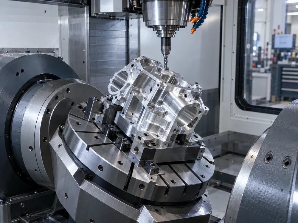
That may help maintain relationships between features that would otherwise be machined in separate orientations.
However, 5-axis machining does not automatically create tighter tolerances.
The result still depends on geometry, workholding, tooling, machine capability, thermal stability, programming, and inspection.
Learn more about our 5-axis CNC machining capabilities.
What Tolerance Can YCS Support?
Tolerance capability should always be evaluated at the feature and project level.
For suitable features and projects, YCS can support tolerances as tight as ±0.005 mm, depending on part geometry, material, machining process, machine capability and condition, thermal stability, and inspection requirements.
This is a project-specific capability, not a default tolerance applied to every feature or part.
A 0.005 mm bilateral tolerance means the finished dimension may vary 5 μm above or below the nominal value.
For example:
20.000 mm ±0.005 mm
gives an acceptable range of:
19.995 mm to 20.005 mm
Whether that requirement is practical depends on the actual feature.
A short accessible diameter and a long flexible wall should not be assumed to have the same tolerance capability simply because the numerical tolerance is identical.
For tight-tolerance projects, manufacturing feasibility and inspection should be reviewed together.
What Is the Difference Between Dimensional Tolerance and GD&T?
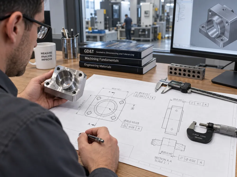
Dimensional tolerances and GD&T both control part variation, but they do different jobs.
Dimensional Tolerance
A dimensional tolerance controls allowable variation in size or distance.
Examples include:
- Length
- Diameter
- Width
- Thickness
- Hole spacing
A dimension such as:
25.000 ±0.020 mm
controls the allowable size range.
GD&T
Geometric Dimensioning and Tolerancing, or GD&T, controls geometry and feature relationships.
Common controls include:
- Flatness
- Parallelism
- Perpendicularity
- Position
- Runout
GD&T can communicate functional relationships more clearly than simply tightening plus/minus dimensions.
For example, a hole may have an acceptable diameter but still fail assembly if its position relative to the datum structure is incorrect.
The correct drawing strategy depends on how the part functions.
What Is ISO 2768?
ISO 2768 is commonly encountered on engineering drawings as a system for general tolerances where individual tolerances are not specified.
It should not be interpreted as “the standard CNC machining tolerance.”
Its purpose is broader: it provides a framework for handling applicable dimensions that do not have their own individually stated tolerance.
ISO 2768-1 and General Dimensional Tolerances
At the time of writing, ISO 2768-1:1989 remains published, although a new edition is under publication.
ISO 2768-1 addresses general tolerances for linear and angular dimensions without individual tolerance indications.
In practical drawing use, an individually specified feature tolerance still takes precedence for that feature.
What Does ISO 2768-m Mean?
The letter m refers to a dimensional tolerance class under ISO 2768-1.
Engineers may encounter drawing notes that reference an ISO 2768 tolerance class to define general requirements for dimensions that are not individually toleranced.
The exact standard and revision cited on the drawing should always be reviewed rather than assumed.
What About ISO 2768-mK?
Legacy drawings may reference ISO 2768-mK.
Historically:
mreferred to a dimensional tolerance class under ISO 2768-1.Kreferred to a geometrical tolerance class associated with ISO 2768-2.
This notation remains important because older drawings may still be in active production.
However, it should not be presented as though both parts of the historical ISO 2768 system remain current without qualification.
2026 Standards Note
At the time of writing:
- ISO 2768-1:1989 remains published, although a replacement edition is under publication.
- ISO 2768-2:1989 has been withdrawn.
- ISO 22081:2021 replaces the former Part 2 approach for general geometrical specifications.
For manufacturing projects, the supplier should review the actual drawing revision and the standards explicitly referenced by the customer.
A legacy drawing and a newly released drawing may therefore require different interpretation.
Because standards change, it is better to verify the applicable edition than to rely on an old tolerance chart copied from another website.
When Should You Specify Tight Tolerances?
Tight tolerances are appropriate when the feature has a functional reason to require them.
Common examples include:
- Bearing interfaces
- Precision bores
- Press or sliding fits
- Locating features
- Sealing surfaces
- Alignment interfaces
- Critical hole locations
- Precision assemblies
- Controlled feature relationships
A feature should not receive a tight tolerance simply because tighter looks more precise on the drawing.
If a non-critical outer profile can vary by a relatively broad amount without affecting function, tightening it may only increase machining and inspection effort.
This principle becomes especially important on complex parts containing both critical and non-critical geometry.
How Are CNC Machining Tolerances Inspected?
The measurement method should match the feature, tolerance, and functional requirement.
Calipers
Calipers are useful for many general dimensional checks.
They are fast and practical, but they are not appropriate for every tight-tolerance requirement.
Micrometers
Micrometers can provide more suitable measurement for controlled external or internal dimensions where their range and geometry are appropriate.
Bore Gauges
Bore gauges can be useful for internal diameters where bore size and variation need closer evaluation.
Height Measurement
Height gauges and related measurement systems can help evaluate feature height and location relative to a reference surface.
Optical Measurement
Optical systems can be useful for small, complex, or difficult-to-contact features.
CMM
Coordinate measuring machines can evaluate complex dimensions, feature relationships, and GD&T requirements when appropriate.
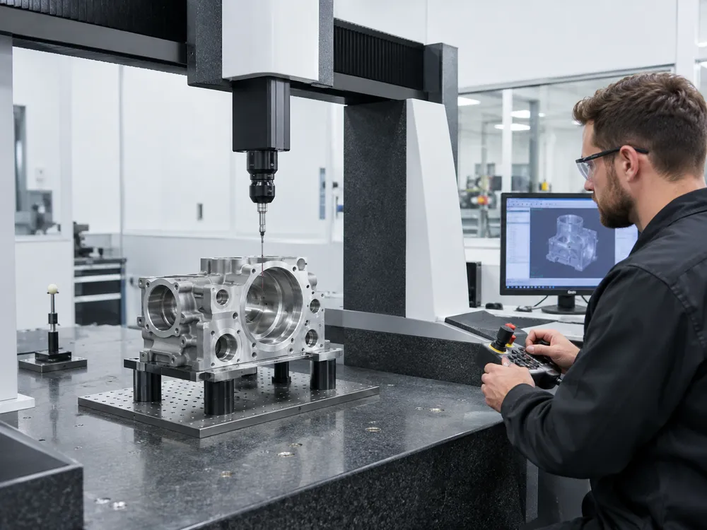
However, using a CMM does not automatically make a measurement correct.
The inspection plan must still consider datum setup, measurement strategy, probe access, part stability, and measurement uncertainty.
Learn more about our quality and inspection approach.
What Is Measurement Uncertainty?
Every measurement has uncertainty.
Inspection equipment, calibration, measurement method, operator technique, environment, feature accessibility, and part condition can all affect the result.
This becomes increasingly important as tolerances become tighter.
A drawing may specify a very small tolerance zone, but the supplier also needs a measurement method capable of distinguishing acceptable variation with sufficient confidence.
That is why machining capability and measurement capability should be evaluated together rather than treated as separate topics.
How Do Thermal Effects Affect Tight Tolerances?
Materials and machine components change dimension as temperature changes.
For general machining, these changes may be insignificant.
For very tight tolerances, they can become relevant.
Potential influences include:
- Heat generated during cutting
- Coolant temperature
- Workpiece temperature
- Machine thermal condition
- Time between machining and inspection
- Inspection environment
Tight-tolerance work may therefore require tighter thermal control during machining and inspection.
This does not mean every precision part requires a specialized temperature-controlled process.
The level of control should match the actual tolerance and measurement requirement.
How Does Surface Finishing Affect Final Tolerance?
Surface treatments can change part dimensions or functional surfaces.
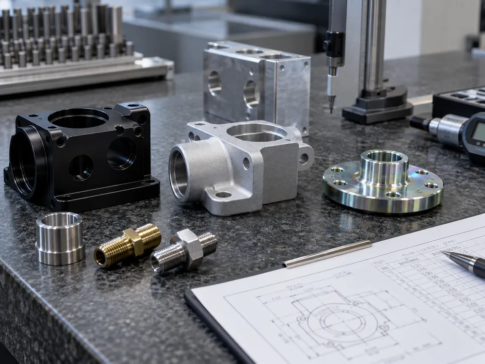
Processes such as anodizing, plating, coating, polishing, or blasting may affect:
- Final size
- Surface condition
- Hole diameter
- Thread fit
- Mating surfaces
- Cosmetic appearance
For critical features, the drawing or RFQ should clarify whether the specified tolerance applies:
- Before finishing
- After finishing
- Or to a selectively masked feature
This should be considered during process planning rather than after machining is complete.
How Do Tight Tolerances Affect CNC Machining Cost?
Tight tolerances can increase manufacturing cost because they may require additional control throughout the process.
Possible cost drivers include:
- More detailed engineering review
- Additional finishing passes
- Slower cutting strategies
- More stable workholding
- Tool wear management
- Additional inspection
- More advanced measurement
- Increased scrap or rework risk
The effect is feature-specific.
A tight tolerance on one accessible critical diameter may be manageable, while applying the same requirement across many difficult features can significantly change the manufacturing route.
This is why over-tolerancing can increase cost without improving function.
For a detailed breakdown, see our CNC Machining Cost Guide.
How Can Engineers Avoid Over-Tolerancing?
Over-tolerancing happens when requirements are tighter than necessary for part function.
It can be reduced through better drawing and DFM decisions.
Tighten Only Functional Features
Identify dimensions that affect assembly, fit, sealing, motion, alignment, or performance.
Do not automatically apply the same tight tolerance to unrelated geometry.
Use Appropriate General Tolerances
A clear general tolerance system can reduce drawing clutter and prevent unnecessary individual callouts.
Define a Clear Datum Strategy
Datums should reflect the functional relationships that matter during manufacturing and inspection.
Avoid Conflicting Requirements
Tolerance notes, title-block requirements, individual dimensions, and GD&T should not contradict each other.
Consider Inspection Access
A feature that is difficult to measure may require a different inspection strategy.
Inspection feasibility should be considered before the drawing is released.
Account for Surface Finishing
If coating or finishing affects a critical dimension, specify whether the requirement applies before or after the process.
Review Difficult Features Early
Thin walls, deep bores, long features, and complex multi-face relationships should be reviewed before production.
Precision should support function, not simply make the drawing look more precise.
What Should You Include on a CNC Machining Drawing?
A clear engineering drawing helps the supplier understand both manufacturing and inspection requirements.
Where applicable, include:
- Drawing revision
- Material and grade
- Critical dimensions
- Individually specified tolerances
- GD&T
- Datum references
- Applicable general tolerance standard
- Surface finish requirements
- Coating or secondary finishing notes
- Thread requirements
- Inspection requirements
- Special functional notes
The 3D CAD model defines geometry, while the 2D drawing communicates controlled engineering requirements.
For quotation, the supplier should receive both when tolerances, GD&T, finishing, or inspection requirements are important.
Frequently Asked Questions About CNC Machining Tolerances
What is the typical tolerance range for CNC machining?
There is no universal tolerance range that applies to every CNC machining supplier, material, feature, process, and part size.
Supplier default tolerances and feature-specific precision capabilities vary. The drawing and functional requirement should determine the tolerance needed for each critical feature.
What is the minimum tolerance for a CNC machine?
A CNC machine does not have one universal “minimum tolerance” that can be guaranteed on every finished part.
Finished-part tolerance depends on machine capability and condition, tooling, geometry, workholding, material, setup strategy, thermal stability, and inspection.
What is a reasonable machining tolerance?
A reasonable machining tolerance is generally the loosest tolerance that still allows the feature to perform its intended function.
Unnecessarily tight tolerances can increase machining and inspection cost without improving the part.
What is the standard tolerance for CNC machining?
There is no single universal standard CNC machining tolerance.
A project may use a supplier default tolerance, a general drawing tolerance, or a feature-specific tolerance. Applicable drawing standards should also be reviewed where referenced.
Can CNC machining achieve ±0.005 mm?
For suitable features and projects, YCS can support tolerances as tight as ±0.005 mm, depending on part geometry, material, machining process, machine capability and condition, thermal stability, and inspection requirements.
This is not a default tolerance for every feature or part.
What is the difference between tolerance and accuracy?
Tolerance is the allowable variation specified by the drawing or engineering requirement.
Accuracy describes how closely the manufactured or measured result corresponds to the intended value.
They are related concepts, but they are not the same thing.
What is ISO 2768?
ISO 2768 is commonly used for general tolerances on engineering drawings where individual tolerances are not specified.
At the time of writing, ISO 2768-1:1989 remains published while a replacement edition is under publication. ISO 2768-2:1989 has been withdrawn and replaced by ISO 22081:2021 for general geometrical specifications.
How are tight CNC tolerances inspected?
The method depends on the feature and tolerance.
Inspection may use micrometers, bore gauges, height measurement, optical systems, CMMs, or other suitable equipment. Measurement capability should be considered together with the machining requirement.
Summary
CNC machining tolerance is a feature-specific engineering requirement, not a single number defined by the machine. Material, geometry, setup, thermal stability, inspection, GD&T, and applicable drawing standards all matter. Specifying only the tolerances needed for function improves manufacturability, inspection clarity, and cost control.
Need a Tight-Tolerance CNC Machining Review?
Send your CAD model, engineering drawing, material, critical tolerances, GD&T, finishing, quantity, and inspection requirements to YCS for a project-specific manufacturing review.