
Design for CNC Machining: A Practical DFM Guide for Engineers
Good design for CNC machining balances part function with tool access, material behavior, workholding, tolerances, inspection, and setup strategy. A part may be technically machinable but still require unnecessary cost or complexity. DFM helps engineers identify these issues before drawings are released for production.
Design for CNC machining means designing a part so its required function can be produced reliably with practical tooling, workholding, setups, tolerances, materials, and inspection methods. CNC DFM considers tool access, internal radii, pocket depth, wall rigidity, holes, datums, surface requirements, and production quantity. The goal is not simply to make a part machinable, but to reduce unnecessary manufacturing effort without compromising engineering function.
A useful DFM review therefore starts with what the part must do, then evaluates whether its geometry and drawing requirements support a stable manufacturing process.
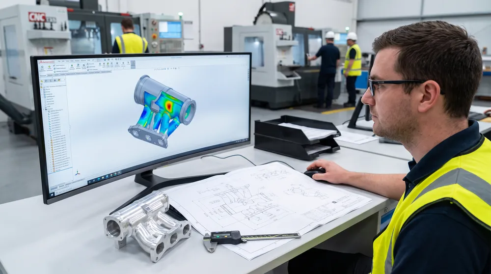
What Is DFM for CNC Machining, and Why Does It Matter?
DFM stands for Design for Manufacturability.
For CNC machining, DFM is the process of reviewing part geometry and engineering requirements to determine whether the component can be produced reliably using practical machining, workholding, tooling, setup, and inspection methods.
This is different from asking only whether a part is physically possible to machine.
A design can be:
Machinable
Technically possible to manufacture.
or:
Manufacturable
Practical to produce with reasonable setup effort, machining stability, inspection confidence, repeatability, and cost.
A deep pocket with difficult tool access may still be machinable. A thin wall with a tight tolerance may also be machinable. But both may require longer tools, slower cutting, special workholding, additional setups, or more detailed inspection.
Good DFM identifies this difference before production begins.
It should not remove functional requirements simply because they are difficult. Instead, it should help engineers distinguish between features that are necessary for part performance and features that create manufacturing effort without improving function.
That means DFM should begin with questions such as:
- Which surfaces locate the part?
- Which dimensions control assembly?
- Which interfaces seal?
- Which features carry load?
- Which holes control alignment?
- Which surfaces are cosmetic?
- Which tolerances affect fit, motion, or performance?
- Which relationships must be preserved during inspection?
Once those priorities are clear, manufacturing decisions become easier.
The objective is not to redesign every part around machining convenience. It is to remove manufacturing difficulty that does not add engineering value.
How Do Tool Access and Feature Geometry Affect CNC Design?
A cutting tool must physically reach the feature it needs to machine.
This is one of the most important principles in design for CNC machining because geometry that looks straightforward in CAD may still require difficult tooling, extra setups, or reduced cutting rigidity.
Tool Access
A feature should be considered together with the direction from which it can be machined.
Holes, pockets, surfaces, and slots located on several sides of a component may require multiple orientations or multi-axis access.
The cutting tool and tool holder also need clearance. A cutter may theoretically reach a surface while the holder, spindle, or adjacent geometry prevents practical access.
Hidden geometry, narrow cavities, obstructed features, and deep surfaces can force the manufacturer to use smaller or longer tools.
Long tool reach reduces rigidity, which can increase vibration, deflection, and sensitivity to cutting conditions.
A useful design question is:
Can a sufficiently rigid tool reach this feature from a practical machining direction?
If the answer is no, manufacturing complexity normally increases.
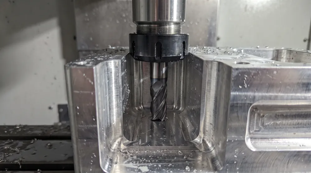
Internal Corners and Radii
Standard CNC milling tools are round, so they naturally create a radius in internal corners.
A smaller internal radius generally requires a smaller cutter. Smaller tools usually remove material more slowly and are less rigid than larger tools.
Where function allows, larger radii can support:
- More rigid tooling
- Higher material-removal efficiency
- Lower tool deflection
- Better process stability
- More practical finishing
There is no single universal internal radius that is correct for every CNC part. The practical choice depends on feature depth, material, geometry, access, and required function.
If a sharp internal corner is functionally necessary, possible approaches may include relief geometry, undercuts, alternative assembly design, EDM, or another project-specific machining strategy.
Deep Pockets
Deep pockets often require longer tools.
The deeper the cutter must extend from the holder, the lower its effective rigidity becomes.
This can affect:
- Wall position
- Surface quality
- Vibration
- Chip evacuation
- Finishing time
- Dimensional stability
Deep pockets can also involve significant material removal and may require multiple tools or slower finishing operations.
The important DFM principle is not that deep pockets should always be avoided.
It is that pocket depth should be justified by function and considered together with tool access, corner radius, material, and surface requirements.
Thin Walls
Thin walls can reduce weight and package size, but they are more sensitive to machining and clamping forces.
A thin section may deflect under cutting pressure, vibrate during machining, or move after material is removed.
Workholding can also distort a flexible feature if clamping forces are not appropriate.
Where function permits, engineers can improve manufacturability by avoiding unnecessarily thin sections, supporting walls with adjacent geometry, and applying tight tolerances only where they are functionally required.
Machining sequence and workholding strategy also become more important as wall rigidity decreases.
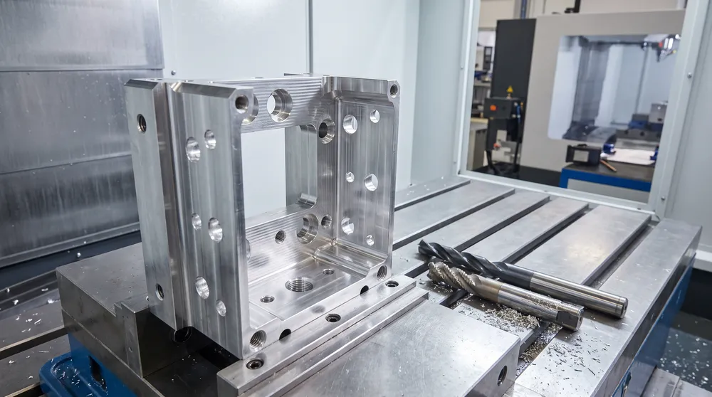
How Should Holes and Threads Be Designed for CNC Machining?
Holes and threads appear simple, but depth, diameter, access, and function can significantly affect manufacturing effort.
Hole Design
Where function permits, conventional hole sizes are generally easier to produce than unusual diameters requiring special tooling or additional interpolation.
As hole depth increases relative to diameter, several issues become more important:
- Chip evacuation
- Tool rigidity
- Cooling
- Straightness
- Tool wear
- Measurement access
A deep small-diameter hole is therefore usually more difficult than a shallow hole of the same diameter.
Blind holes require additional consideration because the total drilled depth, bottom geometry, thread depth, and chip clearance may differ from the functional depth shown on the drawing.
Hole access matters as well. A hole positioned behind another feature or at a difficult angle may require additional setups or special access.
Thread Design
Threads should be designed around function, assembly, access, and practical tooling.
Standard thread forms and sizes are usually easier to tool and inspect than unusual requirements.
For internal threads, engineers should consider:
- Required engagement
- Blind-hole depth
- Tool clearance
- Space below the thread
- Inspection method
- Insert requirements where applicable
Very deep threads can add manufacturing effort without necessarily improving joint performance.
Thread depth should therefore be based on mechanical requirements rather than an assumption that deeper is always better.
How Do Tolerances and Datums Affect CNC Manufacturability?
Tolerance is not only a drawing value.
It directly affects manufacturing strategy, tooling, workholding, finishing, and inspection.
A general dimension with a broad acceptable range may be straightforward to produce.
A critical feature with a tight tolerance may require:
- Additional finishing operations
- More stable workholding
- More careful tool control
- Tighter thermal control
- Additional process checks
- More detailed measurement
That is why tight tolerances should be applied where function requires them rather than distributed across a drawing by default.
For suitable features and projects, YCS can support tolerances as tight as ±0.005 mm, depending on part geometry, material, machining process, machine capability and condition, thermal stability, and inspection requirements.
This is not a default tolerance for every dimension.
For a deeper discussion, see our CNC Machining Tolerances Guide.
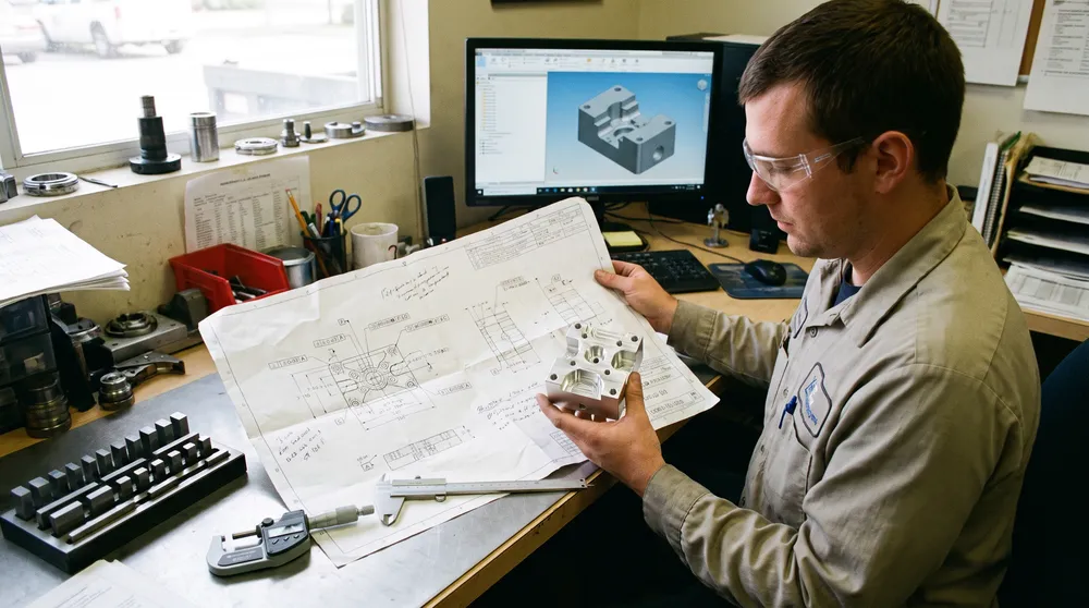
Datum Strategy
Datums communicate how important features relate to each other.
This matters during both manufacturing and inspection.
A drawing should make clear which surfaces or features establish the functional reference system for the part.
Important considerations include:
- Functional datums
- Manufacturing references
- Inspection references
- Relationships between critical features
- Accessibility of datum surfaces
A tight tolerance without a clear datum structure can create ambiguity even when individual dimensions appear precise.
Good DFM therefore considers whether the datum scheme reflects part function and whether the intended relationships can be established reliably during both production and measurement.
How Can Setup Count Be Reduced, and When Does 5-Axis Help?
Every setup adds work beyond the actual cutting operation.
A new setup may require:
- Repositioning
- Re-clamping
- Datum establishment
- Alignment
- Offset verification
- Additional inspection
Some parts genuinely require several setups.
However, unnecessary machining orientations can increase manufacturing effort and create additional datum-transfer steps.
Group Features by Accessible Orientation
Where practical, related features can be designed so they are machined from the same direction.
A small feature added to another face may look minor in CAD but can create an entirely separate setup.
Consider Critical Feature Relationships
If two important features must maintain a precise relationship, producing them in the same stable setup may sometimes simplify control.
Reducing setup count can improve efficiency, but setup reduction should not override functional design requirements.
When 5-Axis Machining Helps
Five-axis CNC machining can provide access to multiple faces and angled features without repeated manual repositioning.
For suitable parts, it may offer:
- Better access to multi-face geometry
- Fewer separate setups
- Less datum transfer
- Better access to angled features
- More efficient machining of related surfaces
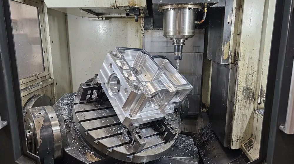
However, 5-axis machining should not be selected simply because it is more advanced.
A straightforward component that can be produced efficiently using 3-axis machining may not benefit from a more complex process.
The useful question is:
Does 5-axis machining reduce the total manufacturing effort for this geometry?
Learn more about our 5-axis CNC machining capabilities.
How Does Material Selection Affect CNC DFM?
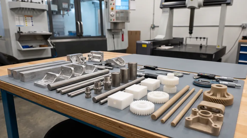
Material selection affects more than mechanical performance.
It can also change cutting forces, heat, tooling, wall stability, clamping strategy, dimensional behavior, and process cost.
Aluminum
Many aluminum alloys machine efficiently, but thin walls, large material-removal ratios, burr formation, and thermal movement can still affect design decisions.
Stainless Steel
Stainless steel can involve higher cutting forces, more heat, and increased tool wear compared with many commonly machined aluminum alloys.
Deep features, small tools, and thin geometry can therefore become more demanding.
Titanium
Titanium can concentrate heat near the cutting zone and often requires careful tooling and process control.
Long-reach tools, difficult access, or extensive material removal may increase machining effort.
POM
POM is an engineering thermoplastic, not a metal.
Heat, clamping force, wall thickness, and material movement should be considered differently from metal machining.
PEEK
PEEK is a high-performance engineering thermoplastic.
Its material value, thermal behavior, and dimensional requirements make stock utilization and stable machining strategy important.
Material should therefore be selected primarily around functional requirements, while DFM evaluates how that material choice affects manufacturing.
How Should Surface Finish and Inspection Be Considered During Design?
Surface requirements can influence machining, finishing, measurement, and cost.
A drawing should distinguish between:
Functional surfaces
Such as sealing, bearing, sliding, locating, or mating interfaces.
and:
Cosmetic surfaces
Where appearance is the primary requirement.
Secondary processes may include anodizing, plating, passivation, blasting, polishing, or other specified treatments.
These processes can affect dimensional planning.
For critical features, engineers should consider whether the tolerance applies before or after finishing.
Masking may also be needed where coating should not affect a thread, bore, interface, or electrical contact surface.
Surface requirements should therefore be defined before quotation rather than treated as an unrelated final step.
Inspection Access
DFM should ask two questions:
Can this feature be machined?
and:
Can this feature be measured reliably?
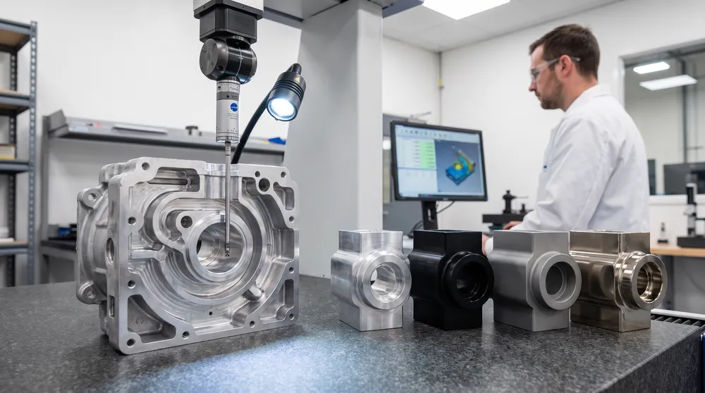
A feature may be accessible to a cutting tool but difficult to inspect.
Examples include:
- Deep internal surfaces
- Narrow bores
- Hidden features
- Complex datum relationships
- Tight dimensions with limited measurement access
Inspection difficulty can affect measurement method, fixturing, reporting, and cost.
The appropriate method depends on feature geometry, tolerance, GD&T, access, and customer requirements.
Depending on the feature, inspection may use calipers, micrometers, bore gauges, height measurement, optical systems, or CMMs.
A feature that cannot be measured reliably can create acceptance ambiguity even if it can be machined.
Learn more about our quality and inspection approach.
How Do Production Quantity and DFM Affect CNC Machining Cost?
A design suitable for a prototype may require a different manufacturing strategy when quantity increases.
For prototypes, priorities may include flexibility, low dedicated tooling, simple workholding, and fast engineering feedback.
For repeat production, additional priorities become more important:
- Repeatable datum location
- Fixture strategy
- Cycle time
- Tool life
- Inspection planning
- Process consistency
- Drawing revision control
The geometry itself may not change, but the most efficient manufacturing route can change with quantity.
For recurring production requirements, see our high-volume CNC machining capabilities.
DFM can also reduce cost by removing manufacturing effort that does not improve part function.
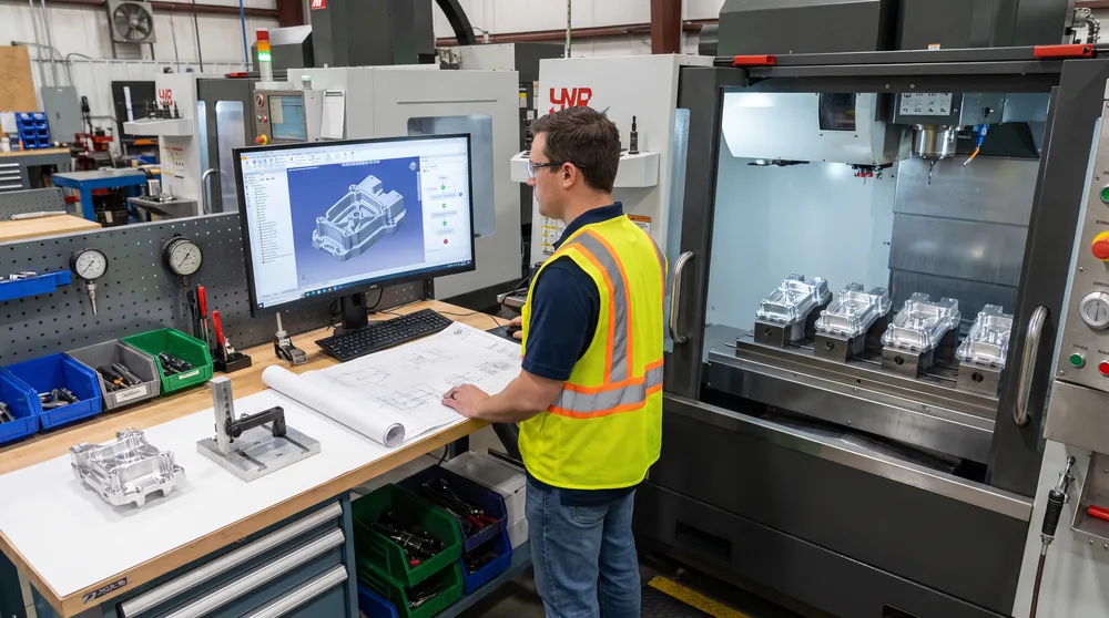
Potential savings may come from:
- Reducing unnecessary setups
- Improving tool access
- Avoiding unnecessarily small cutters
- Simplifying deep pockets
- Using practical internal radii
- Avoiding unnecessary tight tolerances
- Simplifying inspection
- Clarifying finishing requirements
This does not mean every component should be redesigned for the lowest possible price.
A difficult feature may be completely justified by function.
The goal is to identify cost created by geometry or drawing requirements that do not add engineering value.
For a detailed cost breakdown, see our CNC Machining Cost Guide.
Common CNC Design Mistakes to Review Before Release
Before releasing a part for quotation or production, review whether the design contains avoidable manufacturing difficulty.
Common issues include:
- Unnecessary tight tolerances
- Sharp internal corners
- Excessively deep pockets
- Thin unsupported walls
- Poor tool access
- Deep small-diameter holes
- Too many machining orientations
- Ambiguous datums
- Finishing requirements not reflected in dimensions
- Critical features that are difficult to inspect
None of these features is automatically wrong.
The important question is whether each requirement supports the function of the part.
If it does, the manufacturer can plan around it.
If it does not, simplifying the design may reduce machining effort and risk.
CNC Machining DFM Checklist
Before sending a CNC part for quotation, check whether the key engineering decisions are clear:
- Are tight tolerances limited to functionally important features?
- Can cutting tools reach all required machined surfaces?
- Are internal radii practical for the feature depth?
- Are deep pockets functionally necessary?
- Are thin walls sufficiently supported?
- Are holes and threads accessible?
- Is the datum structure clear?
- Can related features be machined in fewer setups?
- Has material behavior been considered?
- Are surface finish and secondary-processing requirements clear?
- Can critical features be inspected reliably?
- Do the 3D CAD model and controlled 2D drawing communicate the same revision and engineering intent?
This checklist does not replace project-specific engineering review, but it can identify many common issues before quotation.
What Should You Send for a CNC DFM Review?
A useful DFM review requires enough information to understand both geometry and function.
Where possible, provide:
- 3D CAD model
- Controlled 2D engineering drawing
- Drawing revision
- Material and grade
- Required quantity
- Critical dimensions
- Tolerances
- GD&T
- Surface finish requirements
- Secondary finishing
- Inspection requirements
- Relevant application information
The CAD model defines geometry.
The 2D drawing communicates controlled engineering requirements such as tolerances, datums, surface specifications, and inspection expectations.
Application context can also help distinguish functional requirements from features that may be adjusted.
DFM feedback should identify manufacturing risk while preserving engineering intent.
Frequently Asked Questions About Design for CNC Machining
DFM for CNC machining is the process of reviewing part geometry and engineering requirements to determine whether the component can be manufactured reliably using practical tooling, workholding, setups, tolerances, materials, and inspection methods.
Start with part function, then evaluate tool access, internal radii, wall rigidity, pocket depth, holes, threads, material behavior, tolerances, datums, setups, finishing, and inspection.
The goal is to make functional requirements clear while avoiding unnecessary manufacturing complexity.
Standard milling cutters are round, so they naturally leave an internal radius.
Smaller internal radii usually require smaller cutters, which may be less rigid and remove material more slowly.
Deep pockets often require longer tools.
Longer tool overhang reduces rigidity and can increase vibration, deflection, chip-evacuation difficulty, and machining time.
Thin walls can flex under cutting and clamping forces and may move after material is removed.
Their manufacturability depends on geometry, material, workholding, machining sequence, and tolerance requirements.
They can.
Tighter tolerances may require more stable setups, additional finishing, tighter process control, and more detailed inspection.
The impact depends on the specific feature and functional requirement.
For suitable multi-face or complex parts, 5-axis machining can improve tool access and reduce repositioning.
However, it is not automatically the most efficient process for every component.
A DFM review is particularly useful before the design is frozen, especially when a part contains deep features, thin walls, tight tolerances, complex datum relationships, multiple machined faces, difficult inspection requirements, or plans for repeat production.
Summary
Design for CNC machining balances function with tool access, rigidity, tolerances, datums, material behavior, setups, finishing, and inspection. Good DFM does not remove necessary engineering requirements; it identifies manufacturing effort that does not improve function. Reviewing these factors before release can improve cost, consistency, and production readiness.
Have a CNC Part Ready for DFM Review?
Send your CAD model, engineering drawing, material, quantity, tolerance, finishing, and inspection requirements to YCS for a manufacturing review focused on practical CNC production.