
CNC-machined aluminum housings often look straightforward, but they can combine deep cavities, relatively thin walls, bosses, threaded holes, mating surfaces, side features, finishing, and inspection requirements in one part. Good DFM helps engineers balance these features before the design reaches production.
Designing an aluminum housing for CNC machining requires balancing wall rigidity, cavity depth, internal radii, bosses, threaded features, tolerances, datum strategy, finishing, and inspection. A housing may be technically machinable but still require unnecessary setups, long tooling, distortion control, or detailed inspection if these features are not considered together during design.
The goal is not to make every housing as simple as possible. It is to preserve the required function while avoiding manufacturing difficulty that does not improve performance.
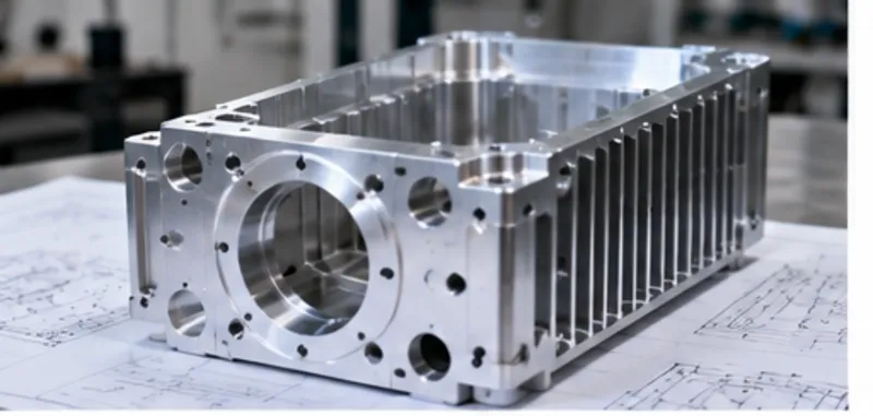
What Makes an Aluminum Housing Difficult to CNC Machine?
A typical machined aluminum housing may start as solid billet or plate stock and require a large amount of material removal. The finished component may contain:
- A deep central cavity
- Thin external or internal walls
- Mounting bosses
- Threaded holes
- Side ports
- Connector openings
- Mating surfaces
- Precision bores
- Cosmetic surfaces
- Features on several faces
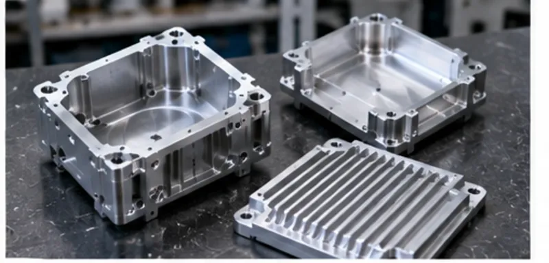
Each feature may be straightforward on its own. The manufacturing difficulty often comes from how they interact.
For example, removing a deep cavity can reduce the rigidity of the remaining walls. A small internal corner radius may then require a smaller and less rigid cutting tool. Tight tolerances on those walls can further increase machining and inspection effort. Likewise, side holes or connector openings can add extra setups if they cannot be reached from the primary machining orientation.
This is why aluminum housing DFM should consider the complete manufacturing route rather than isolated feature rules. For general CNC design principles, see our Design for CNC Machining Guide.
How Should You Design Wall Thickness?
Wall thickness is one of the most important design considerations for CNC-machined housings. There is no universal minimum wall thickness that applies to every aluminum housing. Practical wall design depends on several factors, including:
- Wall height
- Cavity depth
- Overall housing size
- Material
- Workholding
- Machining sequence
- Required tolerance
- Surface finish
- Adjacent features
Wall Rigidity
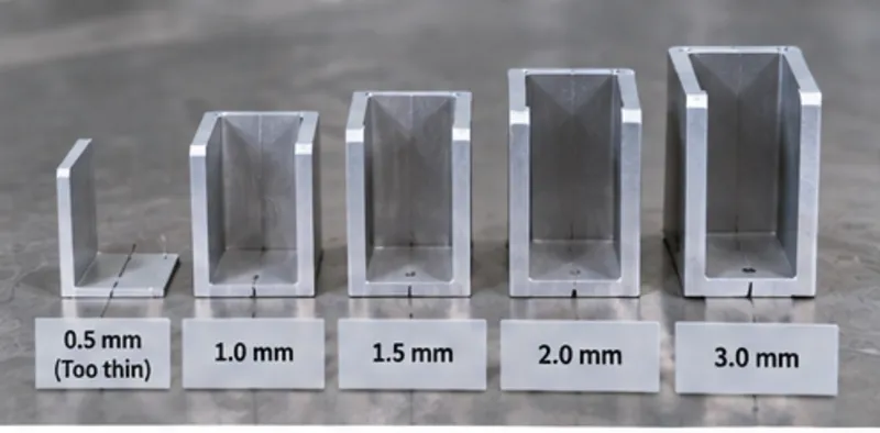
A wall becomes more flexible as it becomes taller and thinner. During machining, cutting forces can cause the wall to deflect away from the tool. Once the cutting force is removed, the wall may partially return toward its original position. This can make dimensional control more difficult.
Clamping Distortion
Workholding forces can also affect thin housing walls. If a flexible housing is clamped while the walls are still heavily supported by surrounding stock, its shape may change as material is removed. If a nearly finished thin-wall housing is clamped too aggressively, the part may distort during machining and relax after release.
Material Removal
Large internal cavities can remove a substantial percentage of the original stock. As material is removed, the stiffness and stress distribution of the part change. For some geometries, staged roughing and finishing strategies may help maintain dimensional stability.
The key design principle is: Wall thickness should be evaluated together with wall height, cavity depth, workholding, and tolerance—not as a standalone number. If a wall does not need to be extremely thin for weight, packaging, thermal, or functional reasons, increasing its rigidity may simplify manufacturing.
How Do Deep Cavities Affect Aluminum Housing Machining?
Deep cavities are one of the defining features of many machined housings. They also create several manufacturing challenges:
Tool Reach
Deeper cavities generally require longer tool reach. As tool overhang increases, rigidity decreases. This can make the cutting process more sensitive to vibration and deflection.
Corner Access
If a deep cavity also has very small internal corner radii, the supplier may need a long, small-diameter cutter. That combination is much more demanding than either feature alone.
Chip Evacuation
Large amounts of material may need to be removed from the cavity. As depth increases, chip evacuation can become more difficult. Poor chip removal can affect cutting stability, heat, tool life, and surface quality.
Remaining Wall Stability & Machining Time
As the cavity becomes deeper, the material left around it may form relatively thin walls that become more flexible as internal stock is removed. A deep cavity may require roughing tools, intermediate tools, finishing tools, multiple depth passes, and additional corner cleanup.
The design question should therefore not be: Is this cavity machinable? A better question is: Does this cavity depth serve the function of the housing, and can it be produced with practical tool access and remaining-wall rigidity?
How Should Internal Corners and Radii Be Designed?
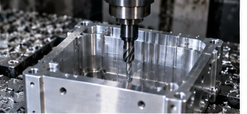
CNC milling tools are round, so internal corners naturally have a radius. This matters particularly in aluminum housings because internal corners are often located at the bottom of deep pockets.
Why Very Small Internal Radii Increase Difficulty
A smaller internal radius generally requires a smaller cutting tool. A smaller cutter is typically less rigid and removes material less efficiently than a larger cutter. If the cavity is also deep, the tool may need both small diameter and long reach—which can increase vibration, deflection, cycle time, and finishing difficulty.
Why Larger Radii Can Help
Where function allows, a larger internal radius may allow the use of a more rigid cutter. This can support better tool stiffness, more efficient material removal, lower deflection, more stable finishing, and longer tool life.
When a Sharp Corner Is Functionally Required
Sometimes a mating component requires additional clearance near a corner. Possible design approaches may include local relief, undercut geometry (e.g. dog-bone / T-bone corner reliefs), changing the mating component geometry, or a secondary machining process. The functional reason should determine whether the extra complexity is justified.
How Should Bosses and Mounting Features Be Designed?
Mounting bosses are common in aluminum housings for PCB mounting, covers, sensors, mechanical interfaces, threaded fasteners, and internal assemblies. A boss should be considered as part of the surrounding cavity geometry, not as an isolated cylinder.
Tool Access Around the Boss
The cutting tool needs space to machine both the boss and the surrounding floor or wall. Very closely spaced bosses can restrict cutter access. A tall boss inside a deep cavity can also require long, narrow tooling.
Boss Rigidity & Transitions
Tall, slender bosses can behave like thin walls and deflect under cutting forces. A boss that grows directly from the cavity floor can be efficient, but the transition geometry should allow practical machining around its base without requiring microscopic corner tools.
Threaded Bosses
If a boss contains a threaded hole, consider thread depth, drilled depth, tool clearance, wall thickness around the thread, assembly load, and inspection access. The design should provide enough material for the intended function without adding unnecessary height or depth.
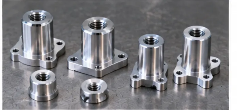
How Should Holes and Threads Be Designed?
Housings often contain more holes than many other CNC part types, including mounting holes, threaded holes, side ports, connector holes, dowel holes, locating holes, and cable-entry features.
Hole Depth & Blind Holes
A shallow hole is generally easier to produce than a deep hole of the same diameter. For blind holes, engineers should distinguish between functional hole depth, drill depth, and thread depth, leaving adequate relief beyond the usable thread.
Side Holes & Threads
Side holes may require repositioning, additional fixtures, indexed machining, or 4-axis / 5-axis access. Standard thread forms and practical thread depths are usually easier to manufacture and inspect. Where thread inserts (such as Helicoil) are required for strength, serviceability, or repeated assembly, that requirement should be defined during design rather than added after machining.
How Should Mating and Sealing Surfaces Be Designed?
Many aluminum housings interface with covers, frames, gaskets, connectors, or other components. Where applicable, these mating surfaces deserve special attention:
- Mating Planes: A cover interface or mounting face may require control of flatness, surface condition, relative height, hole position, and datum relationships.
- Sealing Surfaces: Where a housing uses a gasket or O-ring, the sealing face may require specific flatness or surface finish characteristics.
- Locating Features: If a cover or internal component is located by dowels, bores, shoulders, or reference surfaces, these features may be more critical than the general outer dimensions of the housing.
This is an important DFM principle: Tolerance priority should follow assembly function, not visual importance. A cosmetic outer wall may need far less dimensional control than a hidden locating bore.
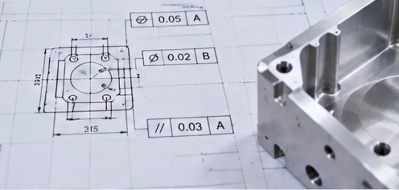
What Tolerances Matter Most on CNC Machined Aluminum Housings?
The most important tolerances on an aluminum housing are usually feature-specific: locating bores, bearing seats, hole position, mounting patterns, connector openings, lid or cover fits, mating surfaces, and sealing surfaces. Applying a tight tolerance to every dimension can increase machining and inspection effort without improving function.
For suitable features and projects, YCS can support tolerances as tight as ±0.005 mm, depending on part geometry, material, machining process, machine capability and condition, thermal stability, and inspection requirements. For a deeper discussion, see our CNC Machining Tolerances Guide.
How Do Datums and Setups Affect Housing Accuracy?
A machined housing may require work on the main cavity, exterior walls, bottom surfaces, side holes, connector openings, mounting features, and cover interfaces. Depending on geometry, these features may be produced across several setups.
Every repositioning step requires the supplier to re-establish the part relative to a manufacturing reference. If critical features span multiple faces, datum strategy becomes important. A clear drawing should communicate functional datums, critical feature relationships, and GD&T where appropriate.
When Can 5-Axis Machining Help Aluminum Housings?
Many housings can be produced efficiently with 3-axis machining and practical repositioning. Five-axis capability becomes worth evaluating when the housing includes:
- Features on several faces
- Angled holes or angled connector openings
- Difficult side access
- Multiple machining orientations
- Critical relationships across faces
- Geometry where setup reduction is valuable
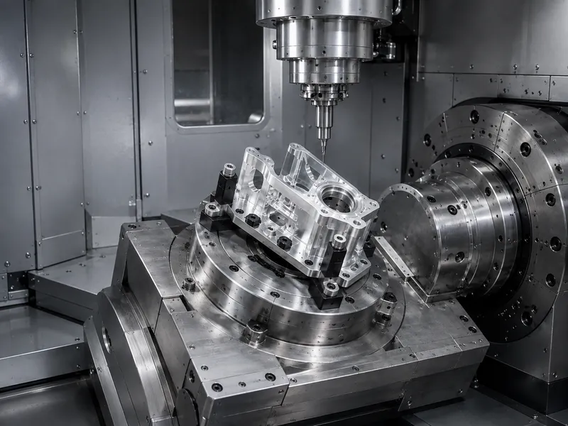
5-axis machining should be selected because it simplifies the manufacturing route, not because it is inherently better than 3-axis machining. For more detail, see our 3-Axis vs 5-Axis CNC Machining Guide and 5-axis CNC machining capabilities.
Which Aluminum Alloys Are Common for CNC Housings?
Alloy selection should begin with functional requirements such as strength, weight, corrosion resistance, machinability, surface finishing, thermal performance, availability, and cost:
| Alloy | Key Advantages | Machinability & Finishing | Common Housing Applications |
|---|---|---|---|
| 6061-T6 | Excellent balance of strength, lightweight, and cost | Superb chip formation; ideal for Type II/III anodizing | Electronics enclosures, brackets, general housings |
| 7075-T6 | Very high tensile strength (comparable to steel) | Good machinability; requires careful anodizing control | Aerospace, defense, and high-stress structural enclosures |
| 5052-H32 | Superior corrosion resistance (marine environments) | Higher ductility; better suited for bending/sheet combinations | Marine enclosures, outdoor electronic cabinets |
6061 Aluminum
6061 is widely used for many CNC-machined housing applications because it offers a useful combination of machinability, mechanical strength, corrosion resistance, availability, and finishing compatibility.
7075 Aluminum
7075 may be selected where higher strength is required. Its use should be based on actual mechanical and project requirements rather than on the assumption that a stronger alloy is always better.
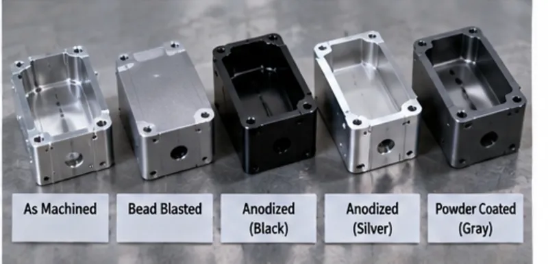
How Does Anodizing and Surface Finishing Affect Housing Design?
Finishing should be considered before the machining drawing is released:
- Critical Dimensions After Finishing: Some finishes can affect the final dimensional condition. If a bore, thread, mating surface, or locating feature must meet a requirement after finishing, the drawing should state that clearly.
- Masking: Threads, electrical contact areas, precision bores, grounding surfaces, and mating interfaces often require masking or protection.
- Cosmetic Surfaces: If appearance matters, identify which surfaces are cosmetic to distinguish visual requirements from purely functional surfaces.
How Are CNC Machined Aluminum Housings Inspected?
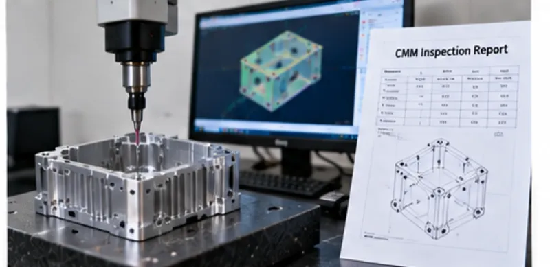
Inspection should focus on the features that control function: flatness, bore diameter, hole position, mounting patterns, mating surfaces, threaded features, datum relationships, and GD&T requirements. Equipment may include calipers, micrometers, bore gauges, thread gauges, optical systems, and coordinate measuring machines (CMM). Learn more about our quality and inspection approach.
What Drives CNC Machined Aluminum Housing Cost?
Housing cost is influenced by stock size, material removal volume, cavity depth, wall thickness, internal corner radii, setup count, side features, tolerances, secondary finishing, inspection scope, and production quantity. For a more detailed breakdown, see our CNC Machining Cost Guide.
Common Aluminum Housing Design Mistakes
- Very thin walls surrounding deep cavities
- Unnecessarily sharp internal corners
- Tall unsupported bosses
- Deep small-diameter threaded holes
- Side features with difficult tool access
- Tight tolerances applied to non-critical geometry
- Undefined mating or sealing requirements
- Finishing not considered in critical dimensions
- Ambiguous datum structure
- Critical features that are difficult to inspect
Aluminum Housing DFM Checklist
- Are wall thickness and cavity depth considered together?
- Can cutting tools reach the full cavity?
- Are internal radii practical for the cavity depth?
- Are mounting bosses accessible and sufficiently supported?
- Are hole and thread depths functionally justified?
- Are side features accessible without unnecessary setups?
- Which surfaces mate with other components?
- Are sealing requirements clearly defined where applicable?
- Which dimensions are functionally critical?
- Are datum relationships clear?
- Can setup count be reduced without compromising function?
- Does finishing affect critical dimensions?
- Are cosmetic surfaces identified?
- Can critical features be inspected reliably?
- Is the selected aluminum alloy appropriate for the application?
Frequently Asked Questions About CNC Machined Aluminum Housings
What is the minimum wall thickness for a CNC machined aluminum housing?
+
There is no universal minimum wall thickness. Practical wall thickness depends on wall height, cavity depth, geometry, material, workholding, machining strategy, and tolerance requirements. A short wall may behave very differently from a tall wall surrounding a deep cavity.
Is 6061 aluminum suitable for CNC housings?
+
Yes, 6061 is widely used for many machined housing applications because of its useful combination of machinability, strength, corrosion resistance, availability, and finishing compatibility. However, alloy selection should follow the functional requirements of the part.
Why are deep cavities difficult to machine?
+
Deep cavities can require longer tools, which reduce rigidity. They may also make chip evacuation more difficult and can leave thinner, more flexible surrounding walls as material is removed.
Can CNC machining produce thin-wall aluminum enclosures?
+
Yes, depending on geometry, material, workholding, machining sequence, tolerance, and inspection requirements. Thin-wall manufacturability should be evaluated on the specific part rather than through one universal thickness rule.
What tolerances are important for aluminum housings?
+
Important tolerances are usually those controlling functional features such as locating bores, mounting patterns, connector openings, mating surfaces, lid interfaces, sealing surfaces, or other critical feature relationships.
Is 5-axis machining necessary for aluminum housings?
+
No. Many aluminum housings can be produced efficiently using 3-axis machining and multiple setups. Five-axis machining becomes useful when additional tool orientation can reduce setups or improve access to multi-face, angled, or difficult geometry.
Does anodizing affect machined dimensions?
+
It can, depending on the anodizing process, feature, and dimensional requirement. If a dimension must meet its tolerance after finishing, that requirement should be clearly stated on the controlled drawing.
Summary
Good aluminum housing design balances cavity depth, wall rigidity, radii, bosses, holes, mating surfaces, tolerances, setups, finishing, and inspection. The goal is not simply to make the housing machinable, but to preserve engineering function while avoiding unnecessary manufacturing effort and ambiguity.
Designing a CNC Machined Aluminum Housing?
Send your CAD model, controlled engineering drawing, material, quantity, tolerance, finishing, and inspection requirements to YCS for a project-specific manufacturing review.