
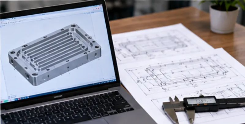
Liquid cold plates may look like simple machined plates, but their manufacturing requirements can be complex. Internal channels, remaining wall thickness, sealing interfaces, inlet and outlet ports, mounting surfaces, flatness, finishing, and inspection all need to work together.
Designing a liquid cold plate for CNC machining means creating flow passages, walls, ports, sealing features, mounting surfaces, and tolerances that can be produced and inspected reliably. Good CNC DFM considers channel access, tool reach, remaining wall thickness, cover interfaces, datum strategy, flatness, finishing, and test requirements without compromising the thermal function of the system.
Thermal and hydraulic performance should be validated for the specific cooling system; this guide focuses on how liquid cold plate geometry affects CNC manufacturability, sealing interfaces, tolerances, finishing, and inspection. A thermally functional design must also be practical to machine, assemble, inspect, and seal.
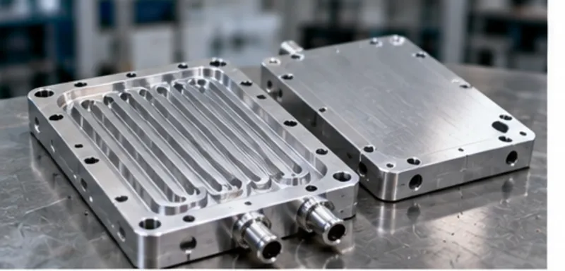
What Is a CNC-Machined Liquid Cold Plate?
A liquid cold plate is a component designed to transfer heat from a heat-generating device into a circulating liquid. Depending on the application, the heat source may interface with one or more machined surfaces on the plate while coolant passes through internal channels or passages.
CNC-machined cold plates may include:
- Machined flow channels
- Inlet and outlet ports
- Mounting holes
- Sealing surfaces
- Cover interfaces
- Threaded features
- Flat mounting areas
- Features on several faces
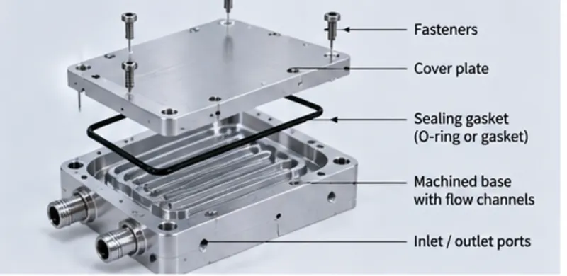
The exact construction varies by project. Some designs use a machined base containing open channels that are later enclosed by a separate cover or another joining strategy. Other designs may use machined grooves or different project-specific constructions.
From a manufacturing perspective, the important question is not only whether the channel pattern can carry liquid. It is whether the geometry can be machined, sealed, assembled, cleaned, inspected, and verified reliably.
How Are Liquid Cold Plates Commonly Constructed?
There is no single construction method for every liquid cold plate. The manufacturing route depends on thermal requirements, pressure requirements, material, geometry, volume, sealing strategy, and production method. Common concepts include:
Machined Base With Internal Passages
A base plate may be CNC machined with channels or cavities that later become enclosed. The design must consider channel accessibility, remaining wall thickness, cover interface, sealing land, port connections, and fastener or joining strategies where applicable.
Machined Grooves Associated With Tubed Structures
Some designs may use machined grooves as part of a broader cooling structure. In these cases, groove geometry, access, wall thickness, and surrounding features still affect manufacturability.
The important DFM principle is: The manufacturing route should be selected around the specific cold plate design rather than forcing every design into one construction method.
How Should Cooling Channel Geometry Be Designed for CNC Manufacturability?
Cooling channels are often the most important manufacturing feature in a machined cold plate. The thermal system designer determines the required flow path, but the geometry must still be practical for machining.
Channel Width and Depth
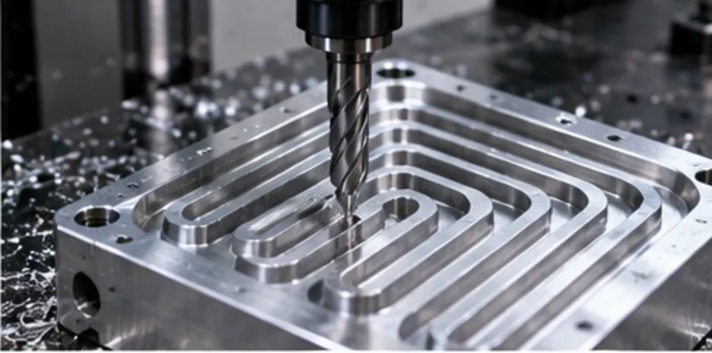
Narrower channels require smaller cutting tools that are less rigid and remove material more slowly. If the channel is both narrow and deep, tool deflection, vibration, and chip evacuation become critical challenges. Practical size depends on material, depth, tool access, required corner radius, plate size, and tolerance.
Internal Radii
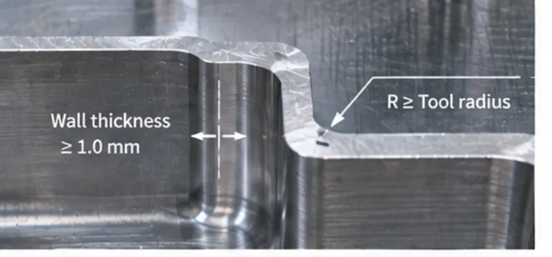
Standard milling cutters are round, so internal channel corners naturally contain radii. Very small internal radii require smaller tools, compounding the challenge of long tool overhang in deep channels. Where thermal function permits, practical internal radii simplify machining and improve process stability.
Channel Intersections and Accessibility
Intersecting passages should be reviewed for cutter access, transition geometry, trapped chips, and cleaning access. A fundamental rule is: A flow path that can be modeled in CAD is not automatically accessible to a cutting tool. Features hidden behind walls or enclosed passages require dedicated manufacturing evaluation. For broader design guidance, see our Design for CNC Machining Guide.
How Should Wall Thickness Around Cooling Channels Be Designed?
Cold plate wall thickness cannot be evaluated as an isolated number. Different regions serve distinct structural and functional purposes:
- Channel-to-Surface Wall: The material remaining between a coolant channel and an external mounting or heat-source surface. A very thin remaining wall is sensitive to cutting forces, clamping distortion, and pressure deflection.
- Channel-to-Channel Wall: Adjacent channels require sufficient material to maintain structural integrity and machining stability without fluttering under cutting pressure.
- Perimeter Wall: Sized not just for fluid containment, but to support sealing lands, bolt patterns, structural mounting, and port connections.
There is no universal minimum wall thickness for every CNC-machined cold plate; practical thickness depends on material alloy, channel depth, plate rigidity, clamping strategy, sealing pressure, and system loads.
How Should the Cover and Sealing Interface Be Designed?
Many cold plate constructions require a cover to seal the machined flow passages. This interface is a manufacturing-critical area requiring attention to mating surface geometry, sealing land width, groove accessibility, fastener clearance, and flatness.
Sealing Land & Gasket Grooves
The sealing land must provide enough usable surface area for the selected sealing method (such as an elastomeric gasket, O-ring, or joining method). Where O-ring grooves are machined, CNC DFM should ensure tool clearance, appropriate corner radii, sufficient distance from mounting holes, and unbroken sealing continuity.
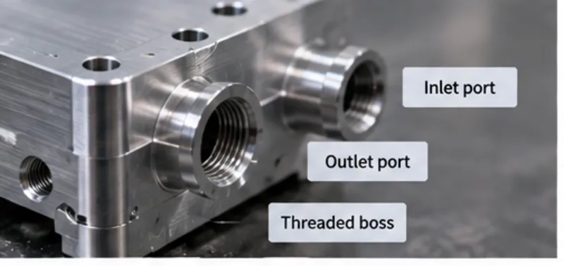
How Should Inlet and Outlet Ports Be Designed?
Ports connect the cold plate to the external liquid circuit. Their placement directly influences machining setups, structural integrity, and assembly convenience.
- Port Location: Provide ample clearance for machining tools, threading taps, external fittings, and assembly wrenches.
- Thread Access: Blind threaded ports require adequate drill relief beyond the usable thread depth.
- Surrounding Material: Ensure thick enough wall stock around the port to withstand fitting installation torque and hydraulic pressure.
- Orientation: Side or angled ports may require additional setups or 4/5-axis indexing. A port that is thermally convenient may still complicate production if access is obstructed.
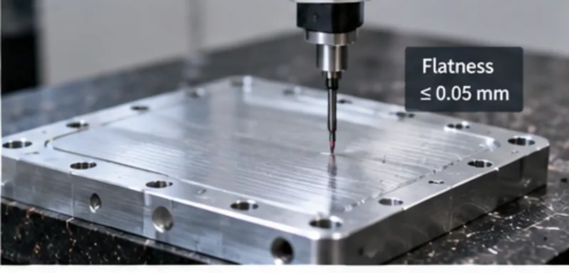
Why Does Cold Plate Flatness Matter?
Flatness directly affects thermal resistance at the heat-source contact surface and leak prevention at the sealing interface. An unnecessarily tight flatness callout increases machining and inspection effort, while large, thin plates may warp due to internal stress release during heavy channel roughing.
For CNC manufacturability, flatness must be evaluated together with plate dimensions, stock thickness, volume of material removed, stress-relief strategies, and workholding methods.
What Tolerances Matter Most on a CNC-Machined Cold Plate?
Cold plate tolerances should be feature-specific rather than applied blanketly across the entire drawing. Critical features typically include port locations, mounting hole patterns, sealing groove dimensions, cover interface steps, and surface flatness across the thermal interface.
For suitable features and projects, YCS can support tolerances as tight as ±0.005 mm, depending on part geometry, material, machining process, machine capability and condition, thermal stability, and inspection requirements. For a detailed guide on tolerancing, see our CNC Machining Tolerances Guide.
How Do Datums and Setups Affect Cold Plate Accuracy?
A cold plate may require machining on multiple faces: internal channel milling, opposite-face heat-sink skimming, side-port boring, and perimeter hole drilling. Each repositioning step requires re-establishing reference datums.
The engineering drawing should communicate functional datum planes (e.g., aligning port holes directly with internal channel centers and mating faces) so the manufacturer can design workholding that preserves those essential relationships.
When Can 5-Axis Machining Help a Liquid Cold Plate?
Many standard cold plates are produced efficiently on 3-axis centers with simple flip fixtures. Five-axis machining becomes advantageous when designs feature side ports, angled fluid entries, compound mounting angles, or complex multi-face geometries where setup consolidation minimizes accumulated datum-transfer errors. Learn more in our 3-Axis vs 5-Axis Guide and review our 5-axis CNC machining capabilities.
Which Materials Are Suitable for CNC-Machined Cold Plates?
Material selection balances thermal conductivity, machinability, structural strength, corrosion compatibility, and weight:
- Aluminum (6061-T6 / 6063): The dominant material choice, providing an optimal balance of high thermal conductivity, excellent machinability, lightweight properties, and broad availability.
- Copper (C11000): Offers significantly higher thermal conductivity than aluminum, but with greater weight, higher raw material costs, and more demanding machining and burr-removal characteristics.
- Stainless Steel: Sometimes utilized for extreme corrosion resistance or specialized cooling fluids, though thermal transfer is substantially lower than aluminum or copper.
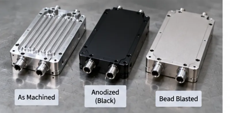
How Do Finishing and Cleanliness Affect Cold Plate Design?
Secondary processing and particle control must be planned before manufacturing begins:
- Surface Finishing: Anodizing or chemical conversion coatings protect exterior surfaces. The drawing must clarify whether critical port threads and sealing surfaces should be masked or coated.
- Internal Cleanliness: Channel geometry should avoid sharp dead-ends or undercut pockets that can trap machining chips and cutting fluids. If validated ultrasonic cleaning or specific particle count limits are required, state them in the RFQ.
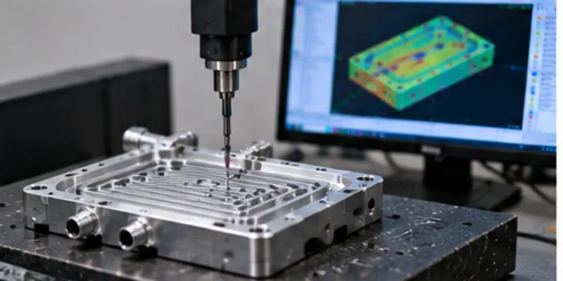
How Should CNC-Machined Cold Plates Be Inspected?
Inspection plans should focus on functional geometry: overall dimensions, mounting patterns, sealing groove depth and width, surface flatness, port thread fits, and GD&T relationships. Metrology equipment includes micrometers, optical comparators, profilometers for surface roughness, and Coordinate Measuring Machines (CMM). Discover more on our Quality & Inspection approach.
What About Leak or Pressure Testing?
Depending on the cooling system specifications, assembled cold plates often undergo hydrostatic or pneumatic leak testing. If pressure verification is required, the RFQ should clearly state the test medium, target test pressure (bar/psi), holding duration, and acceptance criteria. For quoting guidelines, refer to our CNC Machining RFQ Guide.
What Drives CNC-Machined Cold Plate Cost?
Cold plate cost is driven by raw billet size, total material removed, channel depth-to-width ratios, small cutter cycle time, multi-face port setups, flatness requirements, secondary finishing, and pressure testing scope. For a detailed breakdown, see our CNC Machining Cost Guide.
Common Liquid Cold Plate Design Mistakes
- Specifying narrow, deep channels without considering small tool deflection
- Calling for razor-sharp internal corners at the bottom of deep pockets
- Leaving excessively thin webs between densely spaced channels
- Designing flow passages that cannot be reached by standard straight cutters
- Allocating insufficient sealing land width around internal channels
- Placing fluid ports too close to mounting screws or external edges
- Specifying blanket tight flatness without functional need
- Failing to consider chip evacuation and post-machining channel cleaning
CNC Cold Plate DFM Checklist
- Can all internal channels be reached by standard cutting tools?
- Are channel width, depth, and internal radii balanced for tool stiffness?
- Is sufficient wall stock retained between adjacent channels and external faces?
- Are sealing lands wide enough for reliable gasket or O-ring sealing?
- Do fluid ports have ample clearance for fittings and installation wrenches?
- Are mounting hole depths and thread reliefs practical?
- Which specific thermal interfaces require controlled flatness?
- Are functional datums clearly identified on the 2D drawing?
- Are internal channels designed to allow thorough flushing and chip removal?
- Are leak or pressure test parameters defined before quotation?
Frequently Asked Questions About CNC-Machined Liquid Cold Plates
What is a CNC-machined liquid cold plate?
A CNC-machined liquid cold plate is a cooling component that uses precision-machined geometry—such as internal fluid channels, ports, mounting surfaces, and sealing interfaces—to transfer heat from power electronics or devices into a circulating liquid coolant.
How should cooling channels be designed for CNC machining?
Channel width, depth, floor radii, corner intersections, tool access, and cleaning accessibility should be considered together. A flow path modeled in CAD is not automatically machinable if standard cutters cannot reach the geometry without excessive deflection.
Is there a minimum wall thickness around cold plate channels?
There is no universal minimum. Practical wall thickness depends on channel depth, material alloy, plate rigidity, clamping sequence, sealing method, operating pressure, and system structural loads.
Why are narrow, deep channels difficult to machine?
Deep, narrow channels require small-diameter endmills with long overhang. This significantly reduces tool rigidity, increasing tool deflection, vibration (chatter), chip-packing risks, cycle time, and potential tool breakage.
Why does liquid cold plate flatness matter?
Flatness directly affects thermal interface contact resistance between the cold plate and heat-generating electronic modules, as well as joint reliability across perimeter sealing surfaces.
Is 5-axis machining required for a liquid cold plate?
No. Most cold plates can be manufactured on 3-axis CNC centers with 2 to 3 setups. 5-axis machining becomes beneficial when designs include angled fluid ports, side features, or complex multi-face geometries that benefit from setup consolidation.
How are CNC-machined cold plates inspected?
Inspection includes verifying mounting hole positions, surface flatness across thermal contact faces, port thread gauges, sealing land dimensions, and critical GD&T relationships using digital height gauges, optical comparators, and CMMs.
Do liquid cold plates require leak testing?
It depends on the construction and project specifications. If leak or pressure testing is required, the RFQ must define the test medium (air or water), test pressure, dwell time, and acceptance criteria.
Summary
A manufacturable liquid cold plate balances channel geometry, remaining wall thickness, sealing interfaces, ports, flatness, datums, finishing, inspection, and testing requirements. Thermal and hydraulic performance should be validated separately, while CNC DFM ensures the geometry can be machined, assembled, inspected, and controlled reliably.
Designing a CNC-Machined Liquid Cold Plate?
Send your CAD model, controlled engineering drawing, material, quantity, tolerances, finishing, inspection, and testing requirements to YCS for a project-specific manufacturing review.