
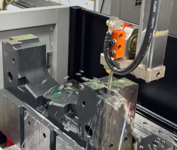
Wire EDM
A continuously fed wire electrode cuts through electrically conductive material along a programmed path.
- Precision through profiles
- Narrow slots and cut features
- Complex outlines in conductive materials
Precision EDM Machining
Wire EDM and sinker EDM support for conductive parts and features that are difficult to produce with conventional cutting tools. YCS reviews geometry, material, tolerance, datum and inspection requirements before selecting the manufacturing route.
EDM at YCS
EDM removes conductive material through controlled electrical discharge rather than direct mechanical cutting. That makes it useful for certain narrow, intricate, hardened or difficult-access features where milling, drilling or turning may not be the best route.
EDM should be selected because it solves a specific manufacturing problem—not because it is automatically more precise or more advanced than conventional machining. The most practical route may use CNC milling, turning, EDM, or a combination of processes depending on the drawing.
EDM Processes
Both processes use electrical discharge, but their geometry and access requirements are different. The part design determines which process should be evaluated.
A continuously fed wire electrode cuts through electrically conductive material along a programmed path.
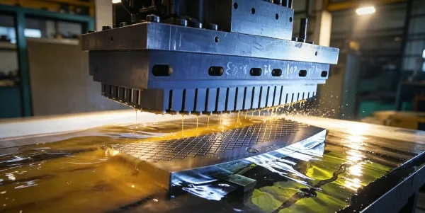
A shaped electrode erodes a corresponding geometry into an electrically conductive workpiece.
Many precision parts are best produced through more than one machining method. Conventional CNC can create accessible geometry efficiently, while EDM is reserved for the features that justify it.
Process Selection
| Requirement | Wire EDM | Sinker EDM |
|---|---|---|
| Through-profile cutting | Often well suited | Usually not the first choice |
| Narrow precision slot | Often suitable when wire access is possible | May be considered for blind/internal geometry |
| Blind cavity | Not suited to a fully blind cavity | Often the process to evaluate |
| Complex profile in conductive material | Suitable when the programmed wire path can pass through the feature | Suitable where electrode geometry can form the required cavity |
| Electrode requirement | Wire electrode | Shaped electrode |
| Best selection basis | Actual geometry, access, material condition, tolerance, surface requirement and total manufacturing route | |
Where EDM Helps
EDM is most valuable when it gives the tool access, feature definition or material-processing route that conventional cutting would struggle to provide efficiently.
Material Requirements
This is an important boundary. Conventional EDM relies on electrical discharge, so the workpiece material must be electrically conductive.
EDM may be evaluated for suitable conductive metal parts depending on the actual material grade, geometry and project requirements.
Hardness, heat treatment, thickness and feature geometry can affect process planning even when the material is electrically conductive.
POM and PEEK are engineering thermoplastics and are not typical conventional EDM workpiece materials. They are generally machined using cutting processes such as milling or turning.
The drawing, conductivity, feature geometry, access and complete process route should be reviewed together before EDM is selected.
Design Review
EDM can solve geometry that conventional cutters cannot produce directly, but it does not eliminate design and process constraints.
Wire EDM requires a viable cut path. Fully blind geometry cannot simply be treated as a wire-cut feature.
Sinker EDM requires an electrode strategy that can form the cavity while maintaining practical access and process control.
Critical EDM features may still need controlled relationships to milled, turned or ground reference features on the same part.
The required surface condition should be specified where it affects function rather than assuming one finish level is appropriate everywhere.
Deep or high-aspect-ratio features can change process time and stability and should be reviewed with the complete geometry.
Deburring, inspection, finishing or other operations may still be needed depending on the part and application.
Tolerance & Quality
EDM is often selected for precision geometry, but the process should not be judged by a generic tolerance claim. The drawing should identify the critical size, location, form, datum and surface requirements that must be verified.
EDM vs Conventional CNC
EDM and conventional cutting are complementary. A project should use each process where it provides a clear manufacturing advantage.
| Design Situation | Process to Evaluate First |
|---|---|
| Accessible pockets, holes and surfaces in machinable material | CNC milling |
| Rotational geometry around a central axis | CNC turning |
| Complex through-profile in conductive material | Wire EDM |
| Blind shaped cavity in conductive material | Sinker EDM |
| Part containing both conventional and difficult-access features | Combined CNC + EDM process planning |
Production Workflow
The exact route changes by project, but EDM work should begin with the drawing and end with inspection of the characteristics that matter.
Confirm material, geometry, revision, critical tolerances, datums and surface requirements.
Decide whether conventional CNC, wire EDM, sinker EDM or a combined route is most practical.
Plan workholding, wire path or electrode strategy, reference features and machining sequence.
Produce the required conductive-material feature using the selected EDM route.
Verify critical characteristics using methods appropriate to the controlled drawing.
Cost Drivers
EDM cost should be evaluated as part of the complete manufacturing route rather than from a machine rate alone.
Profile complexity, cavity shape, slot width, depth and access affect process planning and machine time.
Material condition, section thickness and conductive properties influence the practical EDM route.
Sinker electrode requirements, workholding and datum transfer can add engineering and setup effort.
More demanding feature control or surface requirements can increase machining passes and verification effort.
Complex geometry may require more detailed or specialized measurement planning.
Prototype and repeat-production orders may justify different setup, electrode and inspection strategies.
Why YCS
The value of EDM is strongest when it is integrated with the rest of the machining and inspection route instead of treated as an isolated operation.
Features are reviewed to determine where EDM provides a real manufacturing advantage and where conventional CNC remains more practical.
Datum relationships, tolerances, surface requirements and secondary operations are considered before the process route is locked.
Critical features are planned together with the measurement method needed to verify the controlled drawing.
Request a Manufacturing Review
A controlled technical package helps determine whether wire EDM, sinker EDM or another manufacturing route is the better fit.
Where available, send the current CAD model and controlled drawing together with the requirements that affect the EDM process.
FAQ
Precision EDM Machining
Send your CAD model, engineering drawing, material, quantity, tolerance, datum and inspection requirements to YCS for a project-specific process review.