
Precision Shaft CNC Machining: Runout, Roundness & Surface Finish
Precision shafts often look simpler than housings, cold plates, or complex multi-axis parts. In practice, their performance may depend on several relationships that a diameter tolerance alone does not control. Bearing journals, seal surfaces, shoulders, keyways, and locating diameters may all need to work around the same functional axis.
Precision shaft CNC machining requires control of more than diameter. Functional shaft accuracy may also depend on roundness, straightness, runout, datum relationships, shoulder location, and surface finish. The correct requirements depend on how each journal, seal surface, coupling seat, or locating feature functions in assembly. A shaft can meet its diameter tolerance and still fail if these relationships are not controlled appropriately.
The goal is therefore not to apply the tightest tolerance to every surface.
It is to control the features that determine how the shaft rotates, locates, supports, seals, or transfers load.
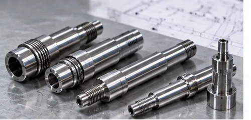
What Is Precision Shaft CNC Machining?
Precision shaft CNC machining is the production of rotational components whose critical diameters, shoulders, grooves, threads, and other features must satisfy defined dimensional and geometric requirements.
Typical shaft features may include:
- Bearing journals
- Seal diameters
- Locating diameters
- Gear or coupling seats
- Threads
- Grooves
- Shoulders
- Keyways
- Flats
- Cross holes
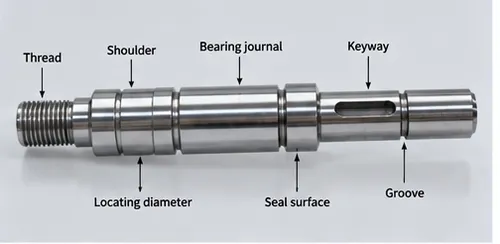
Many shaft features are naturally suited to CNC turning because they are rotationally symmetric around a central axis.
However, a finished shaft may also require milling, drilling, cross-hole machining, threading, or other operations.
What makes a shaft “precision” is not simply a small diameter tolerance.
The important issue is whether the controlled features meet the functional requirements of the assembly.
Why Can a Simple Shaft Be Difficult to Machine?
A simple cylindrical component may be straightforward.
A functional shaft becomes more demanding when several requirements interact.
For example, one shaft may contain:
- Multiple bearing journals
- Different diameters along its length
- A seal surface
- A coupling seat
- Several shoulders
- A keyway
- A cross hole
- Threads at one end
Every individual dimension may appear simple.
The difficulty comes from maintaining the correct relationships between them.
A bearing journal and a coupling diameter may each be within size tolerance but still rotate about slightly different axes.
A long shaft may meet diameter requirements but bend enough to violate straightness or runout requirements.
A seal surface may be dimensionally correct but have an unsuitable surface condition for the selected seal.
This is why shaft drawings should communicate function rather than rely only on plus/minus diameter dimensions.
Diameter Tolerance vs Roundness: What’s the Difference?
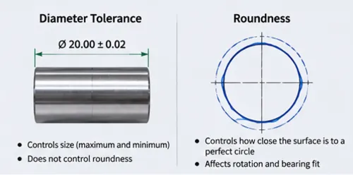
Diameter tolerance and roundness are related, but they control different characteristics.
A diameter tolerance controls the acceptable size of a cylindrical feature.
For example, a journal may have a specified nominal diameter with upper and lower limits.
If measurements remain within those limits, the feature may satisfy its size requirement.
That does not by itself demonstrate compliance with a separately specified roundness requirement.
Diameter Controls Size
A diameter measurement answers:
Is the measured size within the permitted limits?
Roundness Controls Form
Roundness addresses how closely a circular cross-section follows an ideal circle.
A shaft journal can therefore meet its diameter size limits while still needing separate verification if roundness is specified on the drawing.
This distinction becomes important for features such as:
- Bearing journals
- Precision fits
- Seal surfaces
- Rotating interfaces
A micrometer can provide useful diameter measurements, but the inspection method must match the characteristic actually specified on the drawing.
The key principle is:
Meeting the diameter size limits does not by itself demonstrate compliance with a separately specified roundness requirement.
For more background on dimensional and geometric requirements, see our CNC Machining Tolerances Guide.
What Is Shaft Runout and Why Does It Matter?
Runout is especially important when shaft features must rotate relative to a defined datum axis.
A shaft may contain several functional diameters that need to behave as one rotational system.
Examples include:
- Bearing journal
- Seal diameter
- Gear seat
- Pulley seat
- Coupling diameter
If these surfaces do not share the required relationship to the functional axis, the shaft may create vibration, uneven loading, sealing problems, or assembly issues even when every diameter is individually within size tolerance.
Circular Runout
Circular runout evaluates variation at an individual circular section as the feature rotates relative to the specified datum axis.
It can help control the rotational relationship of a surface at a particular section.
Total Runout
Total runout evaluates variation across a broader cylindrical surface as the part rotates relative to the datum axis.
Because it considers the surface over its length, it can address more of the overall rotational behavior of that feature.
The exact GD&T control should follow the functional requirement and drawing standard used by the engineering team.
Functional Datum Axis
Runout is meaningful only when the relevant datum structure is clearly defined.
A drawing should communicate which feature establishes the functional rotational reference.
For example, if a shaft is supported by two bearing journals, the intended datum strategy should reflect how the assembly actually locates and rotates.
This leads to an important rule:
Runout is not simply another name for diameter tolerance, roundness, or concentricity.
Each control communicates a different engineering requirement.
How Does Straightness Affect Precision Shafts?
Straightness becomes increasingly important as shaft length increases relative to diameter.
A short, rigid shaft behaves differently from a long, slender one.
During machining, a longer unsupported section may be more sensitive to:
- Cutting force
- Workholding force
- Tool pressure
- Heat
- Material movement
- Release of internal stress
A shaft can meet individual diameter measurements and still have an axis or surface that is not sufficiently straight for the application.
Straightness can affect:
- Bearing alignment
- Rotation
- Assembly clearance
- Seal behavior
- Coupling alignment
- Runout at distant features
The required straightness should follow function.
Not every shaft needs an extremely tight straightness specification.
Adding tight controls without a functional reason can increase machining and inspection effort unnecessarily.
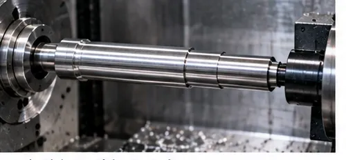
Which Shaft Features Usually Need the Tightest Control?
Not every shaft diameter should receive the same tolerance or surface requirement.
The features that deserve the greatest control are usually those that interact directly with mating components.
Bearing Journals
Bearing journals may require control of:
- Diameter
- Form
- Runout or datum relationship
- Surface condition
- Shoulder position
The exact requirement should follow the bearing system and fit design.
A general-purpose diameter tolerance should not replace the fit requirements defined by the application.
Seal Surfaces
A rotating seal may depend on:
- Diameter
- Surface condition
- Runout
- Form
- Relationship to the working axis
Surface requirements should follow the specific seal design.
There is no universal surface-finish value that is correct for every seal.
Locating Diameters
A locating diameter may establish the position of:
- A gear
- A coupling
- A pulley
- A housing component
- Another rotating element
Its functional relationship to the datum system may be more important than non-functional shaft diameters.
Gear and Coupling Seats
These features may transfer torque or locate rotating components.
Depending on the assembly, important requirements may include:
- Diameter
- Fit
- Shoulder location
- Runout
- Keyway relationship
- Surface condition
Shoulders
Shoulders establish axial position.
Their location and relationship to adjacent journals can therefore affect bearing preload, spacer position, seal position, or assembly stack-up.
A shaft drawing should distinguish these critical interfaces from clearance diameters that may tolerate much more variation.
How Should Shaft Surface Finish Be Specified?
Surface finish should follow function.
It should not be applied uniformly across every shaft surface unless the application genuinely requires it.
A precision shaft may contain several different surface types.
Bearing Journal
The required surface condition should follow the bearing and fit requirements.
Seal Surface
A sealing surface may require a surface condition appropriate to the selected seal and operating environment.
Clearance Diameter
A non-contact diameter may not need the same finish as a bearing seat.
Cosmetic or Non-Functional OD
A surface that does not control fit, motion, sealing, or location may justify a less demanding requirement.
Unnecessarily tight surface-finish requirements can add manufacturing time or additional finishing operations without improving function.
A more useful rule is:
Surface-finish requirements should follow the function of the mating surface.
The drawing should identify critical surfaces clearly rather than forcing the supplier to assume that every turned diameter has the same requirement.
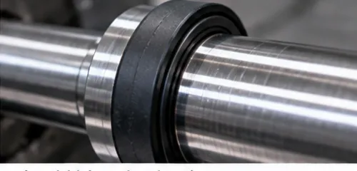
How Do Long and Slender Shafts Affect CNC Machining?
As unsupported shaft length increases relative to diameter, deflection and straightness control generally become more demanding.
A slender workpiece can flex during machining.
Potential influences include:
- Cutting forces
- Clamping
- Workpiece support
- Tool pressure
- Heat
- Material condition
- Machining sequence
Deflection During Cutting
If the shaft bends away from the tool during cutting, the final diameter may vary along its length.
The shaft may also spring back after the cutting force is removed.
Workholding and Support
Depending on the geometry and process, long shafts may require additional support or different workholding strategies.
The appropriate method depends on the equipment, shaft length, diameter, feature layout, and tolerance requirements.
There is no universal length-to-diameter rule that applies to every shaft.
Machining Sequence
Roughing, semi-finishing, and finishing sequence can affect dimensional stability.
Removing large amounts of material from a long shaft may also change stress distribution.
For difficult shafts, process planning should consider the part as a flexible system rather than as a perfectly rigid cylinder.
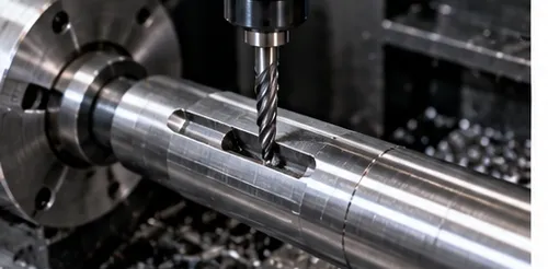
How Do Keyways, Flats, Grooves and Cross Holes Affect the Process?
Many shafts are not purely turned components.
Additional functional features may require secondary machining.
Common examples include:
- Keyways
- Drive flats
- Cross holes
- Retaining-ring grooves
- Oil passages
- Milled slots
- Threaded cross features
These can affect the manufacturing route in several ways.
Additional Setups
A cross hole or keyway may require a different orientation from the primary turning operation.
Feature Relationships
A keyway may need a controlled angular or positional relationship to another feature.
A cross hole may need to align with a flat, groove, or datum.
Deburring
Intersecting holes or milled features can create burrs that need to be addressed.
Inspection
The drawing should make clear whether the feature’s location relative to the shaft axis or another datum is critical.
A shaft that appears to be a turning part may therefore require a combination of turning, milling, drilling, and inspection operations.
This is one reason process planning should be based on the complete drawing rather than the basic outside shape.
For broader part-design guidance, see our Design for CNC Machining Guide.
How Do Datums and Setups Affect Shaft Accuracy?
Datum strategy is especially important when a shaft contains several functional diameters.
The drawing should establish the reference system that best represents how the component works in assembly.
For example, a shaft may rotate primarily on one or more bearing journals.
Other features may then need controlled relationships to that rotational reference.
Important relationships may include:
- Journal-to-journal alignment
- Gear seat to bearing datum
- Seal surface to bearing datum
- Shoulder position
- Keyway location
- Cross-hole position
Multiple machining setups can introduce additional reference-transfer steps.
That does not automatically make the part inaccurate.
It means process planning should preserve the feature relationships that matter.
The engineering drawing should define functional relationships and datums rather than attempting to dictate every machining setup.
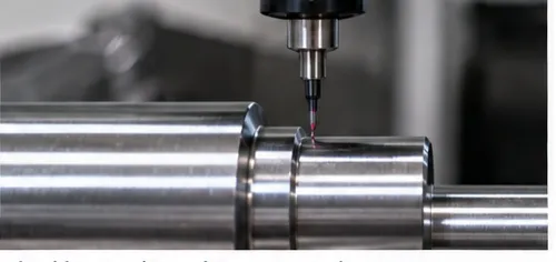
When Is CNC Turning Enough for a Precision Shaft?
CNC turning can produce many precision shaft features directly.
Depending on the part and required specifications, turning may be suitable for:
- Diameters
- Shoulders
- Grooves
- Threads
- Tapers
- Faces
- Other rotational geometry
For many shaft applications, a correctly planned turning process can produce the required dimensions and functional relationships.
However, some requirements may need or benefit from additional processes.
Examples may include especially demanding requirements for:
- Diameter control
- Form
- Runout
- Surface condition
- Hard material condition
- Post-treatment dimensions
The appropriate process should be selected from the actual drawing requirements.
This article therefore does not assume that every precision shaft requires a secondary grinding process, nor does it imply that CNC turning alone is appropriate for every shaft.
The right manufacturing route is project-specific.
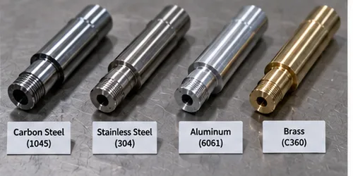
Which Materials Are Common for CNC-Machined Shafts?
Material choice should follow mechanical and environmental requirements.
YCS works with materials including aluminum, stainless steel, and titanium, all of which may appear in shaft-type components depending on the application.
Aluminum
Aluminum can be useful where low weight, corrosion resistance, machinability, or other application-specific properties are important.
However, not every bearing or wear surface is suitable for aluminum.
The material must match the functional loading and mating system.
Stainless Steel
Stainless steel may be selected where corrosion resistance, strength, durability, or environmental exposure matters.
Different grades behave differently during machining, so the exact material should be stated on the drawing or RFQ.
Titanium
Titanium may be used where high specific strength, low weight, or corrosion behavior justifies it.
Its machining strategy differs from aluminum and many steels, particularly in terms of heat, tooling, and process control.
Material selection should therefore begin with the application rather than with machining convenience alone.
How Are Precision Shafts Inspected?
Inspection should match the characteristic specified on the drawing.
No single instrument verifies every shaft requirement.
Diameter
Micrometers and other suitable dimensional equipment may be used to check journal size.
Shoulder Position and Length
Linear dimensions may require appropriate dimensional or coordinate measurement depending on tolerance and geometry.
Roundness
Roundness should be evaluated using a method appropriate to the specified form requirement.
A few diameter measurements alone should not automatically be treated as a complete roundness evaluation.
Runout
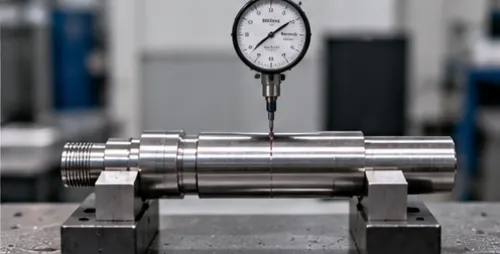
Runout can be evaluated by rotating the part relative to the specified datum reference and measuring surface variation with an appropriate setup.
The inspection method must reproduce the intended datum relationship.
Straightness
Straightness measurement depends on whether the drawing controls a surface element, feature axis, or another defined characteristic.
Threads, Grooves and Keyways
Threads may use suitable gauges or measurement methods.
Keyways, flats, and grooves may require dimensional and positional inspection.
Surface Condition
Surface roughness or other surface requirements should be verified using a suitable method where specified.
The most important principle is:
The inspection method should match the characteristic specified on the drawing.
A shaft should not be accepted or rejected using a measurement method that does not actually evaluate the required characteristic.
Learn more about our quality and inspection approach.
What Drives Precision Shaft Machining Cost?
Precision shaft cost depends on more than overall length and diameter.
Important factors may include:
Material
Material cost, machinability, tool wear, and heat behavior can affect manufacturing effort.
Shaft Length
Longer components may require different workholding, support, and process planning.
Diameter and Stock Size
Starting stock affects material usage and removal volume.
Number of Functional Journals
A shaft with several controlled journals may require more finishing and inspection than a single-diameter shaft.
Tolerances and Geometric Controls
Tighter size, form, straightness, or runout requirements can increase process-control and inspection effort.
Surface Finish
Demanding journal or seal-surface requirements may require additional manufacturing steps.
Additional Features
Keyways, cross holes, flats, grooves, and secondary threaded features may require additional setups or machining operations.
Inspection
Detailed reporting or complex geometric verification adds quality-control scope.
Quantity
Prototype and repeat-production quantities may use different fixture, setup, and inspection strategies.
The goal is not to remove every difficult requirement.
It is to avoid requirements that increase manufacturing effort without improving shaft function.
For more detail, see our CNC Machining Cost Guide.
Common Precision Shaft Drawing Mistakes
Common issues worth reviewing before quotation include:
- Applying tight tolerances to every diameter
- Assuming diameter tolerance demonstrates compliance with a separately specified roundness requirement
- No clear functional datum axis
- Runout referenced to a feature that does not represent assembly function
- Surface-finish requirements applied to every OD without functional need
- Bearing journal requirements left unclear
- Seal-surface requirements not defined
- Keyway or cross-hole relationships not controlled where function requires them
- Long shaft geometry without considering straightness
- Additional finishing requirements introduced after quotation
- Inspection requirements not defined
None of these features is automatically incorrect.
The issue is whether the drawing communicates what actually matters to the assembly.
A good shaft drawing separates functional precision from unnecessary precision.
Precision Shaft DFM Checklist
Before sending a precision shaft for quotation, review the following:
- Which diameters are functionally critical?
- Which features establish the working datum axis?
- Are diameter tolerance and roundness being treated as separate requirements where necessary?
- Is runout required for any bearing, seal, gear, or coupling surface?
- Does shaft straightness affect assembly or rotation?
- Are bearing-journal requirements clearly defined?
- Are seal-surface requirements clearly defined?
- Do shoulders control important axial locations?
- Is surface finish specified only where function requires it?
- Are long or slender sections likely to require additional process planning?
- Are keyways, flats, cross holes, and grooves clearly located?
- Are feature relationships tied to appropriate datums?
- Are post-treatment or final-condition dimensions identified where relevant?
- Can each critical requirement be inspected using a suitable method?
- Do the 3D model and controlled drawing represent the same revision?
A checklist cannot replace project-specific engineering review, but it can reduce ambiguity before machining begins.
For the technical information to include when requesting a quotation, see our CNC Machining RFQ Guide.
Frequently Asked Questions About Precision Shaft CNC Machining
Precision shaft CNC machining is the production of rotational components whose critical diameters, form, runout, straightness, feature relationships, and surface requirements must meet defined functional specifications.
No.
Diameter tolerance controls allowable size variation, while roundness controls circular form.
A shaft journal can satisfy its diameter limits without automatically satisfying a separate roundness requirement.
Runout controls how a surface varies as the shaft rotates relative to a specified datum axis.
It is commonly relevant when bearing journals, seal surfaces, gear seats, or other rotating features must maintain a controlled relationship to the working axis.
Circular runout evaluates rotational variation at individual circular sections.
Total runout evaluates variation across more of the controlled surface as the part rotates relative to the datum axis.
The correct control depends on the functional requirement.
Straightness can affect bearing alignment, rotation, sealing, assembly clearance, coupling alignment, and runout at distant features.
It becomes especially important for longer or more slender shafts.
Features that affect bearing fits, seals, location, torque transfer, axial position, or rotational relationships may require tighter control.
Non-functional clearance diameters often do not need the same tolerance.
No.
The required manufacturing process depends on the specified diameter, form, runout, material condition, and surface-finish requirement.
Some shaft features may be achievable through turning, while other requirements may justify additional finishing processes.
Inspection may include diameter measurement, runout evaluation, straightness, roundness, shoulder location, thread checks, keyway or groove measurement, and surface verification.
The method should match the characteristic defined on the drawing.
Summary
Precision shaft CNC machining is about more than holding diameter. Functional performance may depend on roundness, straightness, runout, datum relationships, shoulder position, and surface finish. The best shaft drawing applies precision where assembly function requires it and defines inspection methods that verify the characteristics that actually matter.
Have a Precision Shaft Project to Review?
Send your CAD model, controlled engineering drawing, material, quantity, tolerances, runout or GD&T requirements, surface specifications, and inspection needs to YCS for a project-specific manufacturing review.